
Guitar Pre-amp Mk2
The second version of the guitar pre-amp adds two more functions, sustain and tremolo. Also the output is designed to be more suitable for driving headphones. The adjustable clipping and bass and treble controls are also included. Initial testing confirms that everything is working as intended, the only concern is that the 'sustain' function seems to add more distortion than expected, and checking the gate voltage on the control jfet it varies over only a small range. Further investigation is needed before deciding on a final circuit, so major changes are possible.
With both sustain and clipping controls at maximum some pickup from the tremolo oscillator can be heard, and the noise becomes audible also, so only one of these effects should be maximum at the same time, otherwise the gain becomes too high. Another problem with excessive gain is that the offset voltage of the second stage is amplified up to a high level at the output, and to avoid this problem an additional coupling capacitor could be added ahead of the tremolo level control.

The op-amp chosen may not be the best choice, so I used sockets on the prototype board to allow some experimentation. The first type to be tried is the TLC082, which has a CMOS input and BJT output. CMOS types are often dismissed as unsuitable for audio use because of poor noise performance, but the TLC08x types are reasonably good, and although they are still not as good as some bipolar and jfet types they should be more than adequate for the present application. The 1/f noise is still relatively poor, so probably not a good idea for phono preamps, but in guitar preamps some bass cut is generally needed, so bass noise is less of an issue. The current drain is higher than I would like, around 15mA total for the complete board, (I was hoping for less than 10mA), but the lower current op-amps I have looked at so far have other problems such as limited output current.
The J112 jfets in TO92 cases were out of stock at my usual supplier, so I bought surface mount versions. When I saw the small size I regretted this, but I managed to solder them in place on the copper side of the board. I strongly recommend the larger case if available. Note that the source and drain are interchangeable, so it only matters that the gate is connected correctly. The BC560 could be replaced by almost any small signal pnp type, these are not critical. The red LEDs I used are type HLMP-1301, but again almost any small low power types should be ok. The 1N914 diodes could be replaced by germanium types such as the OA5 used in the first version, the clipping should be softer then.
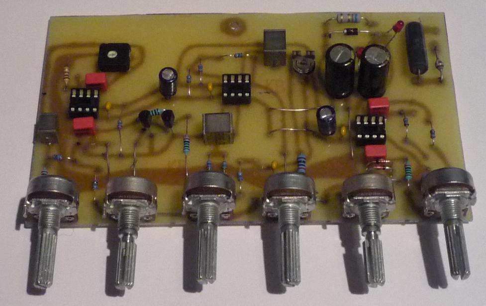
Here is the 'final' board, ready to be wired up and tested. The controls are just cheap potentiometers bought via eBay, but I have used this type before and found them reliable so far. The 2k linear types are most difficult to find, but these can be 2k2 or 2k5 if these are easier to obtain.
References
TLC082 Data. (The input offset voltage is not 60uV as claimed on the first page.)
J112 Data.
BC560 Data.
