There are many possible circuits using feedforward error correction. What these circuits have in common is two or more signals added or subtracted to form the output. The method of adding the signals may be just two resistors connected together, two windings on the same transformer, etc. Subtracting signals can be achieved by applying them to opposite ends of the load, as in a bridge amplifier. Whatever the method employed, the point of this combination of signals is that one of them is of poor quality, e.g. from a class-B amplifier with heavy crossover distortion, and the other signal is derived in such a way that the combination of the two cancels the distortion.
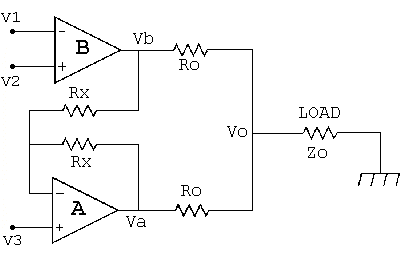
An example follows in which the simplest combination method, using two resistors, is used together with a simplified circuit showing only the essential connections. B is a low quality amplifier and A is a higher quality 'error amplifier'.
For simplicity Ro and Rx have the same values for the two halves of this circuit, but this is not necessary, and sometimes, e.g. in the Quad 'current dumping' circuit, they are not all resistors, and capacitors and inductors can also be used. The input signal to be applied to the load is V3, but for now assume this to be zero, and V1 and V2 are signals which produce output Vb from amplifier B.
Whatever voltage, Vb, appears at the output of B, it is inverted by amplifier A so that Va = -Vb, and added to the original via resistors Ro. The result of this is that Vb is cancelled, and the output Vo across the load is completely independant of amplifier B. It has been assumed that amplifier A has infinite open-loop gain to make Va = -Vb, but a finite gain can be compensated for by adjusting resistor values, adding trimmer capacitors etc., and in principle exact cancellation is possible.
Provided amplifier A remains linear amplifier B serves no purpose at all, and could be left out of the circuit, with its output replaced by zero voltage, or any other voltage. The big problem is to keep A linear, and if it has to supply the whole of the output current this is more difficult than if it has to supply only a small proportion of the current. This is where B can serve a useful purpose.
Although amplifier B has no effect on the voltage across the load it does have one important effect. The output of amplifier A includes two components, one being -Vb as already mentioned, and the other being determined by its own input V3, which is the input signal which we wish to apply to the load. The output current from A is therefore a function of these two components, and a suitable value of Vb can reduce the output current from A to a level where linearity is easy to achieve, e.g. by operation in class-A. In effect amplifier B then supplies most of the output current so that A needs to supply very little.
To summarise, the arrangement shown ensures that B has no effect on the voltage across the load, but by suitable choice of V1 and V2 the current demanded from A can be reduced to such an extent that it can be made highly linear. V1 and V2 can be obtained in several ways, and two examples follow :
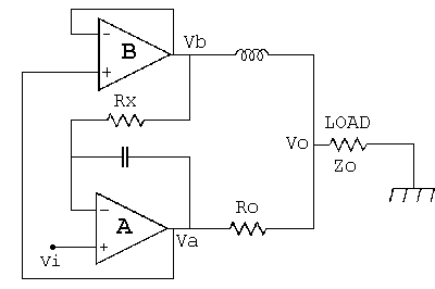
In my own design both A and B are driven from the same driver stage, and B is just a normal class-AB output sub-amplifier which supplies most of the current in one direction, but cuts off for load currents over 100mA in the other direction. A then has to take over and supply the rest of the current. Again a standard class-AB type sub-amplifier is all that is needed for this function, but it remains in class-A.
A few simple changes to the top diagram convert it to my feedforward output stage :
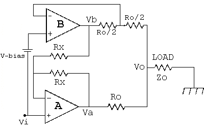
Another variation, in effect a unity gain output stage based on the Quad circuit. Again Vb is cancelled at the load by the output of the error amplifier. In this circuit V2 is obtained from the output of A, and in the original Quad version B was an unbiased class-B output stage :