
Here we are going to make a simple radio controlled device using supplies from your local dumpster. This project should cost less than a dollar to make. If you spend more than a dollar on this project, you need to dig more.
I am so glad that I can spell overview now. That god damn rule never works. Here's the plan: use a cordless telephone and some simple circuitry to make a radio controlled relay that can be used to switch essentially anything in just 5 easy steps.
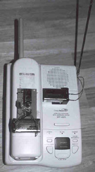
Go to the dumpster and find a cordless phone. Since we will not actually be "calling" the telephone, we need one with the "page or locate" function. The locate function makes the handset ring when you press the locate button on the charging station. So basically, when the phone rings on the locate function, the ringing signals a relay to switch position (from off to on).
The phone I found is a SONY model crapo something. It doesn't really matter. It has an old school answering machine in it, making it potentially fun to listen to all the messages on the tape. But all the messages on this machine seemed to be about this lady that couldn't find the light switch in her basement.
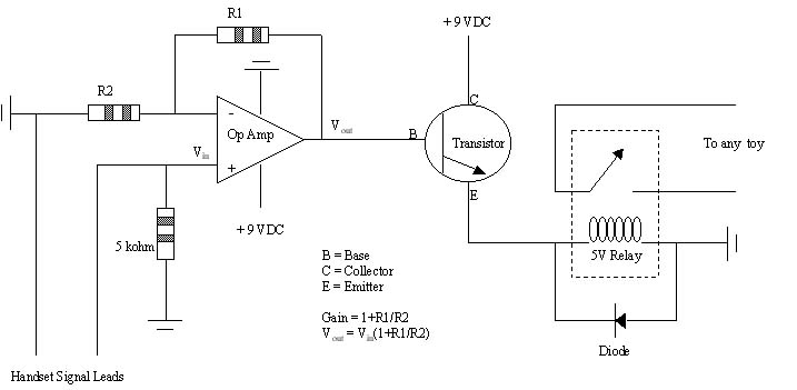 The signal from the handset speaker now needs to be amplified to switch our relay. This is because at most you will get like a volt maybe off the speaker for signal. We're gonna need at least 5 volts to switch a small standard relay. So the first step in amplification is to run the speaker signal through an operational amplifier (op amp). This brings the low voltage speaker signal up to a usable level, say around 5 or six volts depending on the gain we select for the op amp.
Essentially any op amp will work for this application. You can steal them from radioshack or your favorite electronics store. You can also get them for free as samples from a semiconductor manufacturer. Major semiconductor companies will send you loads of free stuff because they want you to use their products for prototypes. And if you use their products for the prototype, chances are you'll use the same product for the main production line and make them lots of big dollars. I was able to get like 50 op amps as free samples online (they even paid shipping). Using the amp is pretty straight forward. You select the gain (gain=ouput voltage/input voltage) by changing the values of two resistors. For the circuit diagram to the right, the gain equals (1+R1/R2). A gain of say 10-100 would be fine for this project. For power, I used a 9 V battery for all the circuitry. You could use the NiCd battery in the phone, but 3.6 V is hardly enough to switch a regular relay.
The op amp boosts the voltage up to around 5-6 Volts, but can only sink a current of like 10 mA. So now we need to use a transistor to beef up the current in order to drive the relay. The output of the op amp is fed directly into the base of your favorite bipolar transistor. I'm using a BU407 because it was a free sample, but you could use almost any medium current transistor like the 2N3055 or TIP31. The transistor now provides ample current to switch the relay. The diode is there to protect the transistor against emf spikes from the relay coil as it is switched off.
The author assumes no liability for any incidental, consequential or other liability from the use of this information. All risks and damages, incidental or otherwise arising from the use or misuse of the information contained herein are entirely the responsibility of the user, have a nice day!
Last updated: 01/01/03