
So basically, the flash circuit will be operating as normal with only one exception. The flash tube will be eliminated and the electrodes will be exposed to a fuel/air mixture environment.
 At this point I would like to mention that getting zapped by a 300 Volt flash capacitor is not going to feel too groovy. So please be careful and try not to make the current path go across your heart.
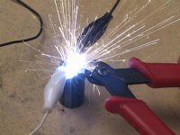
We only need to make three connections to the flash circuitry. First disassemble your camera being careful not to destroy the mechanical shutter system as this triggers the flash. Next take out the battery and locate the main storage capacitor in the camera. It should look like a cylindrical fellow, shaped kind of like a battery. Once you have found this guy, make sure it is discharged by shorting its leads together with a screwdriver. This is gonna make a big ball of sparks if it was charged up, so be careful. Now you need to find the flash tube and remove it. Now I don’t mean remove it with hammer, you need to be gentle. There should be two connections to the tube itself, these are the leads from the main capacitor. Unsolder the flash tube and solder in some wires where the tube used to be. These two wires will go to your electrode system and will carry the charge from the capacitor to the spark gap. Keep these wires short and use a moderate gauge of wire.
At this point I would like to mention that getting zapped by a 300 Volt flash capacitor is not going to feel too groovy. So please be careful and try not to make the current path go across your heart.
We only need to make three connections to the flash circuitry. First disassemble your camera being careful not to destroy the mechanical shutter system as this triggers the flash. Next take out the battery and locate the main storage capacitor in the camera. It should look like a cylindrical fellow, shaped kind of like a battery. Once you have found this guy, make sure it is discharged by shorting its leads together with a screwdriver. This is gonna make a big ball of sparks if it was charged up, so be careful. Now you need to find the flash tube and remove it. Now I don’t mean remove it with hammer, you need to be gentle. There should be two connections to the tube itself, these are the leads from the main capacitor. Unsolder the flash tube and solder in some wires where the tube used to be. These two wires will go to your electrode system and will carry the charge from the capacitor to the spark gap. Keep these wires short and use a moderate gauge of wire.
Once the flash tube has been removed, you need to find the trigger transformer output. The trigger transformer output should be a wire soldered to the flash tube reflector or wrapped around the tube somehow. Solder a wire on to this guy or to the reflector itself. This wire will also go to your electrode system and will initiate the spark. Keep this wire away from any other wires or circuitry as regular wire insulation is not rated for the voltage that this will carry.
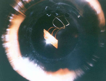
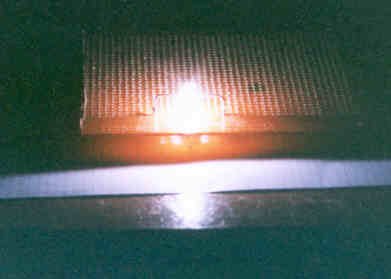
At this point the flash circuit should be hooked up to the electrode jig to make sure the spacing is right and all. If it doesn’t work here, it’s not going to work inside the chamber. Solder up some wire leads to the three electrodes so you can connect them to the flash circuit. Try to keep these wires as short as possible and use a moderate gauge of wire for the capacitor leads to minimize resistance. It doesn’t matter which capacitor lead goes to which side of the electrode jig, as long as the trigger transformer is in the center. So charge it up and adjust the electrodes till you get a nice fat spark. Just be sure to remember to discharge the capacitor before you adjust the electrodes. I'd also like to mention that even if it does "fire", the capacitor will still have like 50 volts across it just waiting for an unexpecting victim.

The author assumes no liability for any incidental, consequential or other liability from the use of this information. All risks and damages, incidental or otherwise arising from the use or misuse of the information contained herein are entirely the responsibility of the user, have a nice day!
Last updated: 5/08/03