
|
|
||
|
41.1 Layout (LightWave.exe) - 1 |
||
 So far I've been concentrating on using the Modeler program almost exclusively. However, I will now be showing you how to use the Layout program to create scenes and animations from your 3D objects. Run the Layout program (Called LightWave.exe on the IBM). First, let me show you a few things about the interface. I may have mentioned some of them before, but it always pays to repeat important things. You can define any viewport to be any type by putting your mouse pointer over that viewport, then pressing a corresponding keyboard shortcut. Keyboard shortcuts that you should memorize: 1 BackThe default view type that Layout starts with is one view port set to 'Perspective' view type. It automatically sets up one 'Distant Light' which it calls 'Light' and one camera. Both point to the center of the world (0 Horizontal, 0 Vertical, 0 Depth), as I've shown before. Here, I've done a 'File->Load->Load Object...' and have loaded the Deinonychus object, which has been brought in with his feet on the ground and centered at the 0,0,0 position (because that's the way I positioned him in Modeler).  However, it's convenient to show three, or even four different views rather than just one. I press 'd' or select 'Layout->Options->Display Options...' to bring up the 'Preferences' requester with the 'Display Options' tab selected. As you can see, under 'Viewport Layout', the default is  , but it can be handy to have three, or even four different views. To select more than one view, select one of the other choices from the 'Viewport Layout' drop-down menu. , but it can be handy to have three, or even four different views. To select more than one view, select one of the other choices from the 'Viewport Layout' drop-down menu. In this case I choose 4 viewports by picking '3 Left, 1 Right', then I define each viewport as I'd like it to be. For the upper-left one I pick 'Right'. Now, with all view types except 'Perspective', the same methods as you used in Modeler may be used. You can hold down the ALT key and click/move with the left mouse button to move the 'Right' view around, for example. Also, when it's not the 'Perspective' view type you can use the Modeler method of pointing with the mouse and pressing 'g' to have the position I point at 'go' to the center of that viewport as I've mentioned before. In the middle-right panel I choose the 'Perspective' view type. As it is, the object is far too small to see, and the view is centered around the object's feet rather than at the center of the object. 
There are inconsistencies, and even the danger of accidently moving or rotating an item if you use Modeler's keyboard shortcut methods to center or move an object within viewports in Layout. The problems are particularly bad when you're dealing with the 'Perspective' view type as the 'g' method to move the object in a view won't work. I'll show you a new method that you can use in the Layout program to position your object within a view's window using this 'Perspective' viewport as an example. Layout has supplied you, in the upper-right of the viewport panel, four buttons which the manual calls 'View Control Drag Buttons'. 
The first button, called 'Center', is a toggle  , meaning that when it's depressed , meaning that when it's depressed  , the view then acts different than it used to. , the view then acts different than it used to.After toggling this button, the viewport continually centers the viewport on the selected item with the pivot point at the center. You can still accidently move an item with this button depressed, so be careful. The next button, called 'Move'  , moves your point of view horizontally when you point your left mouse at this button, hold the left mouse button down and drag left and right. It will move in and out if you move your mouse forward and back. , moves your point of view horizontally when you point your left mouse at this button, hold the left mouse button down and drag left and right. It will move in and out if you move your mouse forward and back.You change your point of view vertically by doing the same thing, but you use the right mouse button, instead. Dragging up or down raises or lowers your point of view. Moving the mouse left or right with the right mouse button pressed does nothing. Be VERY CAREFUL that you have your mouse positioned over this button when you click and drag as it's very easy to move an item when doing this. If you don't have your mouse over the button, you could drag a tiny bone around without even knowing it, for example. The next button, 'Rotate',  , only works with the 'Perspective' view type. It's ghosted if it's an orthogonal (straight-on) view type like 'Right'. , only works with the 'Perspective' view type. It's ghosted if it's an orthogonal (straight-on) view type like 'Right'.The last button, 'Zoom',  , Zooms the point of view more magnified or less magnified without moving it left or right. Both the left and right mouse buttons do the same thing. Moving the mouse toward you zooms, moving the mouse away from you makes it smaller. Moving sideways does nothing. , Zooms the point of view more magnified or less magnified without moving it left or right. Both the left and right mouse buttons do the same thing. Moving the mouse toward you zooms, moving the mouse away from you makes it smaller. Moving sideways does nothing.In the bottom-left I put 'Schematic' view. I'll be showing how to set up the schematic view so you can more easily select the bones you need to use in an upcoming tutorial. Finally, I choose 'Camera' view for the large right-hand view. 
After you've done this, and you save the scene, from then on THAT SCENE ONLY will be set up with four viewports. The next time you load that scene, it will automatically display four viewports just the way you set them up. So, you can either configure Layout to show you a single viewport (the default) or from two to four viewports at once . If you select more than one viewport, you can toggle the 'One Viewport' / 'Multiple Viewports' mode by pressing the '0' key. One rather annoying thing is that the Modeler program, as opposed to the Layout program, uses the 1 - 9 and 0 keys to change between layers instead of selecting the view type for a view as they do when you're in the Layout program. In the Modeler program, pressing '1' selects layer 1, pressing '2' selects layer 2, up to '0' which selects you layer 10. So, if you think you're in the Layout program when you're actually in Modeler, suddenly it will look like your object disappeared if you press '0' thinking you're going to flip to one viewport from four viewports. It would have been nice if these two programmers had gotten together and arranged to have the keyboard shortcuts equal each other (which, at some times, they do). If that happens to you, just look at the layers gadget and select the layer you'd been working on before you pressed the '0' key (or any other of the 1 - 9 keys). Layout, WHAT I'VE ALREADY COVERED SO FAR In previous tutorials I've shown how to set up lights, direct the camera, convert skelegons to bones, render a scene and set some options. Why have I avoided explaining in more detail the features of the Layout program until now? Well, most people start with the Layout program instead of starting with Modeler. They find objects to use on disks or the internet and, thus, never learn to use Modeler. Since this entire book is about organic modeling, Modeler comes first and Layout comes second. When building models, it's very important that you finish all skelegons, adjust all bank rotation handles, name and fill all weight maps before you delve deeper into using the Layout program. If you don't do this, you'll find that you'll either be redoing things a hundred times in Layout such as bone rotations. You'll find that it's much like building a house of cards when dealing with the Layout program. Giving one example, you can't build a schematic view of your bones if you're continually deleting all bones and starting over because you forgot to create one skelegon. A schematic view will disappear the instant that you delete your bones. Ideally, you want all bones done and all weight maps properly assigned and tested before you truly begin creating a scene with the Layout program. When you have as many as 60 bones, this can make an enormous difference in time, so make sure you have everything done BEFORE you start building a complex scene with Layout (you'll have to build experimental scenes with simple light sources and camera angles to test your weight maps, but I mean continuing with your scene beyond what I've already shown you). If you've come this far, congratulations. You've done well (unless you've jumped ahead, thinking you're doing yourself a favor by coming here first. In that case, go back to the Modeler section and learn how to use Modeler first. It takes skill to build a house of cards... skill that you can only get through practice and diligence). Layout, DEINONYCHUS SETUP As I've shown before, set up three lights and position the camera.  I select  and ensure that the proper object is selected. and ensure that the proper object is selected. I open up the  and make sure that the Deinonychus object is selected. and make sure that the Deinonychus object is selected. ... then click  and chose 'Hide Selected Items' and chose 'Hide Selected Items' Layout, CONVERTING SKELEGONS I, next, convert skelegons to bones by selecting 'Add->Bones->Convert Skelegons to Bones...' from the 'Create' tab.   Layout, CREATING A SCHEMATIC VIEW You should create a schematic view ONLY after you have tested each skelegon to make sure they've each been flipped in the proper direction so they hinge properly, and checked to make sure that you've created every skelegon that your object will need (including any specialty skelegons such as puller skelegons that you might need for setting up IK goals, rotation skelegons that might be needed to rotate hands separate from moving the hand's positions, or transposition skelegons which are used to move a hand or foot separate from its rotation). The reason for this is, if you delete the bones from your object, which you have to do if you add a new skelegon to your object, or flip an existing skelegon... the detailed schematic you make will disappear. A schematic view can take an hour to create, so you don't want it disappearing on you. "What is a schematic view?" you might ask. A schematic view shows each bone and item of an object as a name in a box. You pick any viewport to display the current schematic view with the drop-down menu just as you'd pick 'Front' or 'Right' view. The instant that you do a 'Convert Skelegons to Bones', all bones are added to the schematic view.  It's up to me to untangle this mess of boxes. For example, I drag each box of the arm until it looks a little like Deinon's left arm. 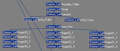  When in schematic view, a line passes from any child to its parent. This is, therefore, a good way of observing child/parent relationships. Once complete, I'll be using this schematic view to quickly select particular bones without having to mess with the perspective view, which oftentimes doesn't select the bone you expected. Layout, POSITIONING SCHEMATIC VIEW BOXES When creating a schematic view, it's best to switch to one viewport as you'll need all the space you can get. I press the zero key to switch to 'Single View' and select 'Schematic View' from the viewport drop-down menu.  Little-by-little, without actually seeing the names for anything, I rearrange all boxes so that all children are beneath their parents. To move a box, I hold the mouse pointer over the box, left-click the box, press and hold the left mouse button, then drag the box to its new position. I select three random boxes, dragging those boxes to the left of the main line of boxes where I start seeing parent/child relationships between those boxes. The three selected boxes in this image were the ones I moved to the left.  In this case, the child is below its parent. In this image, I've moved the selected box to be beneath its parent box. I can tell by watching the connecting line. 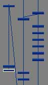  After you've moved three or four boxes away from the center, you generally start seeing parent/child relationships by watching how the lines connect with each other as you move the boxes. You keep doing this until all child boxes are beneath their parents. As you untangle the mess LightWave made, you'll oftentimes have to drag pieces that you've figured out to the side so they're out of the way of other boxes. When you drag a box, children of that box will move along with that box, and they'll hold the relationship they had with each other in the schematic as you drag the box. Thus, when you find a parent that's high up the child/parent chain you'll find that a lot of other boxes will move together. When you've find this type of parent, move it away from the rest of the boxes. Keep dragging boxes until all child/parent line point straight down from the parent to their child boxes. Layout, PARENT/CHILD RELATIONSHIPS When you create skelegons in Modeler, once they're imported into Layout and turned into bones, Layout automatically will parent the bones relative to how they were connected as skelegons head-to-toe. However, in Layout, bones don't need to be head-to-toe to work. In fact, you might choose the heel bone to be a parent to the object, and create one other bone somewhere around the hip which all other bone sequences are childs of. The advantage of parenting this way, you can move the whole body MINUS THE FEET so the feet stay planted on the ground. You can then set up the shin and thigh bones using IK rather than FK so the knees automatically choose their angles. But, there is no particular reason that any bone need necessarily be a child of the one above it. AND, two bones don't need to be physically touching each other end-to-end for them to be a parent/child pair. This means that if you don't need to actually move the hip bones, for example, then don't you don't need hip bones. The leg bones can be child of the end of the backbone even if there were a large gap between the end of the backbone and the end of the leg bone. However, it isn't in Modeler that this can be done. In modeler, skelegons automatically will be parented head-to-tail, head-to-tail, on down the chain. If a new set of skelegons is begun, those will be parented to the object, itself. You can use the schematic view to redo parent/child relationships. So, lets re-parent some bones. This is where the 'house of cards' idea starts coming clear. As you start to diverge away from the skelegon information, the more that the scene takes on aspects which are separate from the skelegons, and particular to Layout's bones. IMPORTANT - After you do a 'Convert Skelegons to Bones', anything that you do to those bones after that moment will not be automatically refreshed unless you again do a 'Delete Bones' and then 'Convert Skelegons to Bones' again. Thus, if you reparent bones, this is the first card placed on the Layout house. If you forgot to create a skelegon, or you didn't create a weight map for that skelegon, or you didn't flip the skelegon in the right direction... You'll either then have to physically make that change in Layout, or delete all bones and start over. So, the first card you laid was the creation of the schematic view, because IF you delete all bones, then all work you did on the Schematic view will disappear. So, I can't stress strongly enough, MAKE SURE ALL SKELEGONS ARE COMPLETE, WITH NO PROBLEMS, BEFORE CONVERTING THEM TO BONES. And, also before you create a schematic view, and before you record pivot rotations, and before you set rest positions... Layout, CHANGING PARENT/CHILD IN SCHEMATIC VIEW I hide the body polygons by pressing 'F1' to bring up the selecting the object (Deinon_With_300mm_WeightMaps21), then clicking and choosing 'Hide Selected Items' as I've said before.I'll choose the Deinon_Root bone from the 'Bones' drop-down menu.  Notice that by the direction of each skelegon, all skelegons are designed to hinge around the Deinon_Root bone. (The small end of each bone points towards 'Deinon_Root') To redfine a parent/child relationship, point to the box you wish to reparent, highlight what will become the child box, hold CTRL key down and click on the parent. The parent/child line will change to show the new parent/child line. Thus, at the moment, I have many separate skelegon chains. Notice in the picture that neither the shoulders, nor the hips, connect to other skelegons. Therefore, those have to be separate skelegon chains. Therefore, when you convert skelegons to bones, they will automatically be parented to the object rather than to other skelegons. However, I want the arms, legs, backbone and tail all parented to the 'Deinon_Root' bone, not to the main object. I'll just show one example of reparenting. I increase the size of the schematic view by pressing '>', then readjust the positioning of the boxes by holding down the ALT key and dragging while holding down the left mouse button. Currently, you can see that the 'Deinon_Backbone' is parented to the object.  Thus, when you tell Layout to reparent a bone to a different position in the 3D world, you have to also tell Layout that you want to keep the same relative position in the 3D World that that bone had before. This is called 'Parent in Place'. Lightwave calculates the SRT offset required to keep the selected object in the "same worldspace" (an item's relationship to the LightWave world relative to its relationship to another item). You must ensure that 'Parent in Place' is turned on before you reparent bones. I press 'o' for the 'General Options' requester. About half-way down you'll see 'Parent in Place'. Make sure it has a checkmark next to it.  So, with the 'Deinon_Backbone' box highlit, I hold down the CTRL key and click with my left mouse button on the 'Deinon_Root' box.  However, you aren't seeing what's happening to the object because I've got the object hidden. When you reparent a bone, it still has the rest position for that bone set to what it used to be. therefore, that bone's weight maps will think that you just moved the arm. Therefore, you must record the rest position for that bone by pressing 'r' before you continue or strange stretchings will occur to the polygons which that bone controls in your object. Once you press 'r', the body will again look correct and work properly. I continue, reparenting all other skelegon chains to 'Deinon_Root' with 'Parent in Place turned on. I finish each bone's reparenting by pressing 'r' to rethink that bone's 'Rest Positon' before I move on to the next bone. You should always check to make sure your object looks correct. Since you won't generally be reparenting more than about 5 or 6 bones, you might turn on visibility on the object after each bone to ensure that nothing is twisted, then save the scene with a new name because Layout has no undo (or one level of undo for limited operations). Then... turn visibility off on the object once more to reparent the next bone. IMPORTANT - 'Parent in Place' ONLY WORKS IF YOU HAVE NEVER ROTATED THAT BONE BEFORE. Therefore, you must reparent bones BEFORE you record their rest positions. If you follow exactly what I said to do, and bones twist your object? Most likely you had already rotated those bones away from their original positions with 'Record Pivot Rotation', and thus 'Parent in Place' isn't working. So, only 'Record Pivot Rotation' AFTER you've reparented bones (This is like building the house of cards, one-by-one. Beware that the house of cards is very senstive to the order in which you place those cards). Another thing I should mention, notice that at the very top of the 'Deinon_RightBicep' bone, you'll see a barely discernable bone which I've called 'Deinon_RightShoulder_Puller'.  Here's the left arm's parenting after I'm done. I've moved all other bone parenting out of the way so you can see it clearer.  Layout, RECORDING PIVOT ROTATIONS AND REST POSITIONS Now, if and only if you've properly tested all skelegons and ensured that they are properly parented child-to-proper-parent, you could continune as I showed in the last tutorial, making sure that  is selected and turned on, making sure that I'm on frame zero, selecting each bone one-by-one, 'Record Pivot Rotation' for each one, then selecting 'Set Rest Position' by pressing 'r' for all 70 of the converted bones. is selected and turned on, making sure that I'm on frame zero, selecting each bone one-by-one, 'Record Pivot Rotation' for each one, then selecting 'Set Rest Position' by pressing 'r' for all 70 of the converted bones.It's always best to select the  tool when you record the pivot rotations on bones. If the 'Move' tool were selected, a bone might change position as you click on a bone to select it. tool when you record the pivot rotations on bones. If the 'Move' tool were selected, a bone might change position as you click on a bone to select it.Are you starting to see why I make sure that everything's complete in Modeler before I start using Layout? I do a 'File->Save->Save Scene As...' and save the scene with the same scene number as the object has. Layout, ANIMATING DEINONYCHUS So, we're finally ready to do some animating. Lets say that you've completed the Deinonychus model, have created and positioned all skelegons, have adjusted all bank rotation handles, have associated weight map names, you've filled those weight maps and created simple scenes to test the movement of each weight map and bone. Now, and only now, are you ready to learn animation. Layout, ROTATING AN OBJECT First, I make sure that 'Auto Key' is turned off. 'Auto Key' can be handy, like when you're Recording Pivot Rotations, but it can also cause problems when you've forgotten that it's turned on. I'm first going to rotate the dinosaur 360 degrees. I wish to have him rotate at a rather slow speed so I create a few frames by typing 240 into the right-hand frame gadget and press RETURN to have Layout take the value. The highest frame count number now reflects the 240 value.  I click with my left mouse button, holding the mouse button down, and drag the frame counter from 0 to 240.  I select the object, select , then enter 360 into the H (Heading) gadget of the Rotate gadget (you don't have to type either the .00 or the degree sign). When I press RETURN, it takes that as the new Heading rotation angle. Because 360 degrees would rotate the object completely around, it doesn't look any different than it did before and it's still pointing in the same direction. If I didn't create a key for the change I did, it would forget the rotation if I moved the frame gadget or rendered the scene so I click the  button. A requester appears. button. A requester appears. Since I wish to just create a key for the selected object at frame 240, I click 'OK'. If I move the frame gadget out of the way, I can now see that a tiny yellow line has appeared at frame 240 on the frame line to indicate that that object has a key set at that frame.  If I change the view type to  , then move the frame gadget to frame , then move the frame gadget to frame  , the object rotates in the view. , the object rotates in the view.Layout, MOVING THE CAMERA As well as moving the object, or a part of the object, you can also move the camera. I select  , then move the frame pointer to frame 10. , then move the frame pointer to frame 10.I select the 'Move' tool and by clicking the left mouse button, holding it down, and moving the mouse forward and backward I can make the camera receed or approach. Using the right mouse button in the same manner I can make the camera go up or down. After I've done a move on any item I click to have Layout remember my change.In the same manner I can 'Rotate' the camera. I select the 'Rotate' tool. The left mouse button makes the camera rotate to the right or left, the right mouse button makes the camera rotate up or down. Sometimes it's easier to switch to a side or top view when rotating or moving the camera. If you make changes to a frame, but DON'T DO A CREATE KEY, and you don't have 'Auto Key' turned on then you can undo any changes you made by just moving the frame gadget to a different frame. All changes will be forgotten and it will revert back to whatever position or angle it was at before you changed it. This only works if you haven't yet clicked on 'Create Key' and you don't have 'Auto Key' turned on. In this same manner I can do what is called a 'fly around'. This acts like you're in an airplane and you're flying around your object. In this way I set the camera at various locations around the object, keeping the object centered in the frame each time, and thus create a fly-around.  Just by doing a 360 degree rotation coupled up with the camera moving to different locations and angles, this creates a very nice animation. At any time you can 'Scrub' the frame gadget back and forth to see what your changes look like. You scrub the frame gadget by clicking on it with your left mouse button, holding the button down and dragging the mouse left and right. Layout, CREATING AN AVI ANIMATION It's now time to create a fly-around animation. If you can scrub the frame gadget, and your objects move, then you can create an AVI animation of it. Depending on how detailed your object is, how many polygons it has, how many frames are in your animation and whether you've turned on the more time-consuming features such as 'antialiasing', it might take a few minutes to render, or it might take all night. First, I have to set some rendering options. From the  drop-down menu I select 'Rendering Options'. drop-down menu I select 'Rendering Options'. When creating an AVI animation, there are many important things here that need to be set. You need to set the first and last frames for the animation. In this case, my last frame will be frame 240. If you're doing an experimental AVI animation just to see if you know how to do it, start with something like 10 frames. That should let you see if you have everything set correctly. In my case I have set reflectivity a little bit in the eyes, and I want the shadows to interplay across the surface as the three lights hit the arms and legs so I turn on 'Ray Trace Shadows' and 'Ray Trace Reflections' and turn off 'Show Rendering in Progress' to speed things up on the long rendering sequence. 'Auto Frame Advance' must be turned on if I don't want to have to automate the process. Next, I need to tell it what kind of animation to create and where to write it. I select the  tab. tab. I set 'AVI(.avi)' as the type of animation.  I click  and pick the most common AVI format, which is free because Microsoft bundles it with their operating systems, 'Cinepak Codec by Radius'. and pick the most common AVI format, which is free because Microsoft bundles it with their operating systems, 'Cinepak Codec by Radius'. I checkmark 'Save Animation', then click the 'Animation File' button to set the filename.  A regular file requester appears. I choose a folder and type 'Deinon.avi' into the 'File Name' gadget, then click 'Save'. I'm almost ready to render now. I close the 'Render Options' window by clicking the close gadget (red X). Some camera options need to be set to tell Layout what size to make the animation. I select the 'Frame Size' button from the 'Camera' tab and enter my preferred size, which is 640 x 480. If you want the animation to be less choppy, you can try 320 x 240. If it will be a final render for high quality output I turn on a 'Medium' level of 'Antialiasing', this will reduce stair-stepping around the edges and make it look smoother when it turns. Antialiasing greatly expands the amount of time that it takes to create the animation so only turn it on when you're absolutely sure it will be your final version. Until everything's working properly, you can render just one frame by presssing the 'F9' key. After it renders like you'd like, you can then begin writing the animation by pressing 'F10' (Render Scene). If you did everything right, it will start ticking off each frame as it renders it and when it's done, a finished animation will appear where you told it to write it. To see what frame it's currently rendering check the 'Frame in Progress' value. |
||
