
Update 11.01.2004: Added a few new pictures from a weekend's work. See them below.
The Line Stage is largely based on the Gary Pimm's BBMCCCS loaded #26 pre amp at http://home.pacifier.com/%7Egpimm/26_battery_biased_mosfet_linestage.gif.
3 inputs, 2 outputs using the "Mu" output on the BBMCCCS to provide a low impedance driving source. The amp will consist of separate PSU and Amplifier parts.
The PSU, in short, features; choke-input, separate transformers for heaters and B+, AC heating for the triodes, heavy RFI/EMI shielding / filtering and shunt regulated B+ for the linestage. The choke input has been critically damped with a series resistor on the choke.
This preamp is currently under construction, and below are a couple of pictures to document the progress.

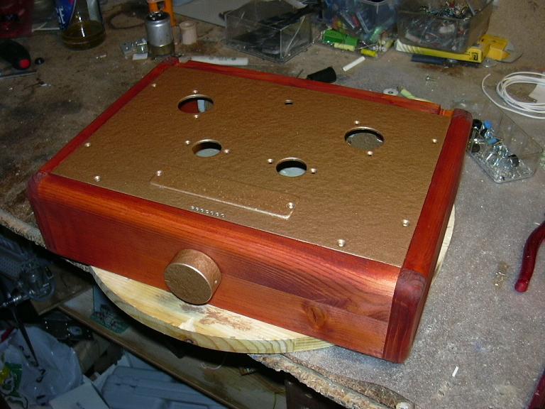
A top plate to carry the line-stage part was fashioned from an old traffic sign!


This is as far as I've got in 3 days or so. The two extra holes in the front will be used for a potential split-channel PSU. (2 extra 0A2 tubes). Input selector is put in the back. This will give a very short signal path to the tubes.
11.01.2004: Some more pictures from the still ongoing construction. Wood and frame still need some sanding and painting. Top plate will be a Hammerite Copper color, and the wood will be oiled or lackered. or something.


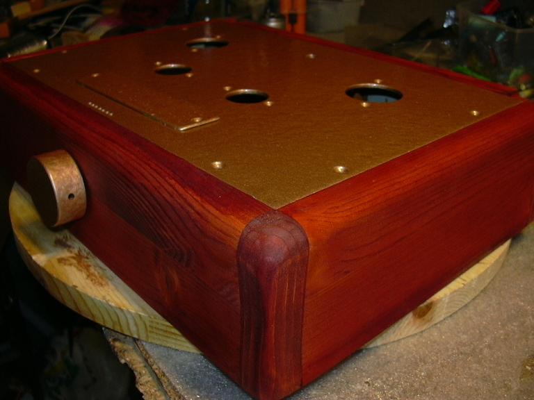
01.02.04: This weekend I did some more work on the preamplifier. The top plate got 2 layers of Hammerite Copper pain, and the wooden frame have a very nice Cherry red shade. The wooden sides and the front have a slight curve inwards (profile), though its not easy to see on the pictures. All in all Im very satisefied with the results :) I hope it will sound as good as i looks! :)

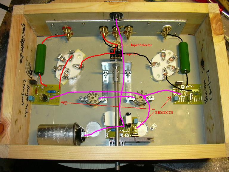
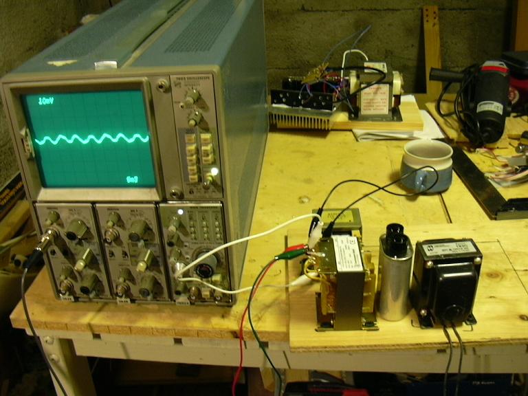
11.01.2004: And now for some upskirts, under the hood pics (the real fun:); The lower one shows some wiring overview. Note the very short signal path!!! (black and red lines)
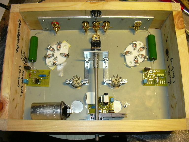
The pics right below shows the PSU. Filament TX in upper left corner (home made), then Power Tx under it and to the right is the Hammond Choke. Used my oscilloscope hooked on the choke and tried different positions to get minimum interference from the filament and power TX'es. I have used a plywood plate for the bottom, and covered if with a 0,2mm thick copper plate.
The cap to the left is a 1uF oil filled snubber cap I cound in a microwave oven :) The right cap is (for now) a JJ 50+50uF cap.

Below are some pictures of the construction of the B+ cable. Ingredients are 0,5mm silver-plated Solid Core copper with Tefzel insulation (wire-wrap wire!!) and teflon sleeving. This will make the cable able to withstand the ~350 Volts of the B+.


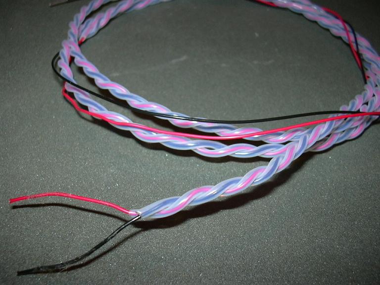
Used my drill to nicely twist the cables.

As connector I have used an XLR plug. The typical rating for these are 250V AC, but my experience is that they can tolerate a lot more. (DC at least. They are obiously tested at 1500V AC).