
# Some power and
refrigeration cycles
#
Vapor power cycles
A power cycle continuously converts heat into work, in which a working fluid repeatedly performs a succession of processes.
In the vapor power cycles, the working fluid, which is water, undergoes a change of phase.

Heat is transferred to water in the boiler from an external source to raise steam, the high pressure, high temperature steam leaving the boiler expands in the turbine to produce shaft work, the steam leaving the turbine, condenses into water in the condenser rejecting heat and then the water is pumped back to boiler. In these vapor power cycle a fixed mass of water undergoes a thermodynamic cycle composed of four processes in the four SSSF devices and continuously converts heat to work.
For a control mass flowing in this power plant,
From first law, we can write,

hence, the efficiency of the vapor power cycle can be given by,
![]()
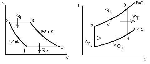
When all four processes in the vapor power cycle are assumed to ideal, the cycle is called a Rankine cycle, in which the four processes are
Boiler: reversible isobaric expansion of steam
Turbine: reversible adiabatic expansion of steam
Condenser: reversible isobaric heat rejection
Pump: reversible adiabatic compression
This cycle is a reversible cycle and can be plotted on the P-v, T-s, and h-s planes.

The steam entering the turbine can be dry (1), wet (1”), or superheated (1’).
Since, all the devices used are, SSSF devices, for 1 kg of working fluid,
For Boiler:
![]()
for turbine:
![]()
for condenser:
![]()
for pump:
![]()
hence efficiency of Rankine Cycle is
![]()
The pump handles liquid water; which is incompressible. So, for reversible adiabatic compression, from property relation,

since, change in specific volume is negligible,
![]()
usually, the pump
work is quite small compared to the turbine work and is sometimes neglected.
Then
![]() , and the approx. cycle efficiency becomes,
, and the approx. cycle efficiency becomes,
![]()
# Effects of
Temperature and Pressure on Rankine cycle efficiency
In attempt to increase Rankine cycle efficiency, two main properties can be altered.
Increasing the boiler operation pressure, as shown in the T-s diagram, can increase efficiency of the Rankine cycle

In the figure the dark green area is the area decreased and light green area is the area increased when the boiler pressure of the Rankine cycle is increased. Area increased in the cycle is clearly more than the area decreased in the previous cycle so Rankine efficiency is increased. But this leads to decrease of quality of steam that comes out of turbine. This quality should not be less than 85%, which limits to maximum pressure of the power plant.
Increasing the maximum operating temperature can also increase efficiency, as this takes steam to the superheated region, which increases the area and also enhances the quality of steam exiting the turbine.

The maximum temperature is limited by the metallurgical quality of the pipes of boiler.
#
Air standard cycles
It consists of two reversible isotherms and two reversible adiabatics.

The working fluid is air, which behaves like ideal gas in perfect conditions.
So for 1 kg gas,
Applying first law for the two isothermal processes, we get

Hence it is again seen that the efficiency of Carnot cycle is the function of its higher and lower absolute temperatures of its reservoirs only.
For many working engines the working fluid is mostly gas. But these gases don’t go through complete thermodynamic cycles, so such engines operate on open cycle. For analysis of such engines closed cycles are devised which closely approximates the open cycles.
This cycle is the for a simple gas turbine power plant. This is the same kind of cycle as Rankine but for this case air is used as the working fluid. Gas turbine power plants are used to generate power in places where air and fuel are abundant, not fresh water. Also, the popular jet engines operate in this cycle.

A gas turbine power plant consists of a compressor where air is first compressed adiabatically. The air then enters the combustion chamber where fuel is burnt at constant pressure and then the products of combustion is expanded in the turbine adiabatically to ambient pressure and thrown out to the surrounding, if it is a open cycle gas turbine, or passed through a condenser for isobaric heat rejection and again to be sent back to the compressor.
If all these processes are done ideally in a closed cycle, then it is called the Brayton Cycle.
Therefore, a Brayton cycle consists of two reversible isobars and two reversible adiabatics.
so, heat supplied,
![]()
and heat rejected,
![]()
Therefore, Cycle efficiency,

For processes 1-2 and 3-4, we have
Pvg=k and Pv=RT
Now on solving we get,

The ratio [v1/v2]
is called the Compression Ratio and is denoted by rk.
Also [P2/ P1] is defined as Pressure Ratio.

Therefore, efficiency of Brayton Cycle is a function of pressure ratio or compression ratio only.
#
Internal Combustion Engine
In
internal combustion engines, the working fluid doesn’t undergo a complete
thermodynamic cycle.
In
an air standard cycle, a certain mass of air operates in a complete
thermodynamic cycle, where heat is added and rejected with external heat
reservoirs, and all the processes in the cycle are reversible.
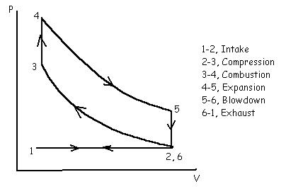
This
is the air standard cycle for spark ignition engine.
Mechanical
cycle for any four stroke S.I. engine will be
Otto
cycle corresponding to such engine has two reversible adiabatics and two
reversible isochors.

Expression
of efficiency of Otto cycle
Let,
m is the mass of air undergoing the cycle of operations.

Where,[
rk ] is the compression ratio and rk=V1/V2=v1/v2.
Therefore,
efficiency of Otto cycle is function of compression ratio only.
This
is the air standard cycle for Compression Ignition Engines in which compression
or air is done and fuel is injected when ignition is desired.
Mechanical
cycle for compression ignition engine

This
engine cycle is completed in four strokes of the piston or two revolutions of
the crankshaft.
The
air standard cycle for such C.I. engine is the diesel cycle. The cycle is
composed of two reversible adiabatics, one reversible isobar and one reversible
isochore.

Efficiency
Analysis:
For
m kg of air in the cylinder,

#
Comparison between Otto and Diesel Cycles

Form
figure we can see that for same compression ratio and heat rejection net area
inside the cycle is less of Diesel cycle and more for Otto cycle. Since on the
P-V diagram we know that the net area covered represents the value of net amount
of work done by the cycle, for same amount of heat rejection in process, 5-1, we
conclude that efficiency of Otto cycle is more than that of Diesel cycle.

From
figure we can see that for same maximum Pressure and Temperature, net area
inside the cycle is more for Diesel Cycle and less for Otto Cycle. Since, net
area covered by the Diesel cycle is more for same amount for heat rejection, it
has more efficiency that the Otto cycle.
This
comparison is of greater importance, since the Diesel Cycle would definitely
have a higher compression ratio that the Otto cycle.
