This bike is for sale. Check the drop down menu for details.
Part of the fun of owning a Harley is doing your own customizing and being able to say that you did it yourself.
HAVE YOU GOT THE RIGHT LENGTH THROTTLE AND IDLE CABLES, BRAKE CABLE AND CLUTCH CABLE? CHECK THE DROP DOWN MENU ABOVE FOR THE BARNETT CABLE MEASURING GUIDE. IT'S REALLY HELPFUL!!!
TAKE THE TIME TO VIEW THE FATBOY I HAVE FOR SALE TOO!!! BIG PIX!!!
Typical installation of 20 inch apehangers on 1996-04 Softail in factory configuration requires cables that are 12 inches over stock length.
New cables and new brake lines? When buying new bars, a rough formula to follow is to measure the increased height + 1/2 the increased pullback that the new bars will give you. This amount will be very close to how much additional cable and brake line that you may need. However, the best method is to fit the new bars to the motorcycle and then make the increased length determinations, if needed at all.
This install does not include the turn signal wiring. The stock configuration of the turn signal wiring allows for reinstalling the turn signals on the forks or a headlight nacelle with light bar.
Handlebar wiring extensions are easy to install. It takes about 4 hours by yourself with ordinary tools and includes the installation of clutch cable, throttle and idle cables, and longer front brake line. These instructions are for wiring installation only. Remember that replacing the clutch cable requires draining the transmission fluid and removing the transmission cover. If you need new throttle/idle cables, replace them when the tank is removed. This project is best done when the fuel tank is empty. Otherwise you have to drain the fuel and go through the hassle of storing it in another container.
Next, disconnect the fuel line from the right half fuel tank. Remove the mounting bolts and grommets from the front of the tank and remove the right side fuel tank.
Remove all connections from the fuel petcock on the left tank and remove the bolt and rubber grommet at the front of the left tank. This will free the left tank for removal. Set it aside. You will find the handlebar wiring connectors along the frame that the fuel tank covered. If you are also extending cruise control wiring, you will find the aux connectors here also. Remove ALL the cable ties that secure the wiring harness to the frame.
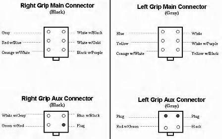
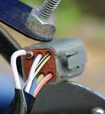
There are six wires coming from each switch housing. They are connected using Deutsch plugs.(Fig. A)
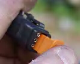
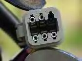
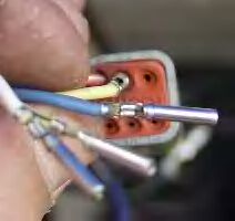
To unplug them, you will have to press a tab. Roll off the rubber gasket and pop the orange cap off the end of the plug.(Fig. B) The cap also serves as a pin lock. Using a small screwdriver you should be able to pry down the pinlocks so the wiring pins can be removed from the plug.(Fig. C) The pins can now be easily removed.(Fig. D)
Do the same thing for both left and right side connectors. Follow the same process with the turn signal wiring, (Purple, gray and black wires)radio and cruise control.
With the wires and pins removed from the plugs, it should be easy to pull the wiring up through the handlebars.
Remove the left handgrip from existing handlebars and loosen the switch housings and clamps on both sides. Remove both handlebar switch housings and the wiring attached to them. If your handlebar wiring is mounted outside of the bars, you need to remove all wire ties that hold the wiring in place. If the wiring is run through the bars, carefully remove it by pulling on the wire, not on the housing.
NOW REMOVE THE OLD HANDLEBARS....
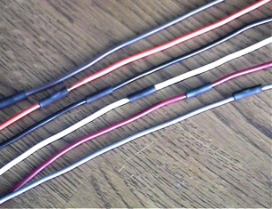
For installation with internal wiring. On a large table, set your 2 switch sets and wiring out. Your switch sets have 6 wires apiece ending with the pins that attach to the Deutsch connectors. WRITE DOWN THE COLOR CODING OF THE WIRES. THE PINS MUST PLUG BACK INTO THE SAME HOLES THEY CAME OUT OF OR YOU WILL HAVE PROBLEMS. Remove enough of the stock vinyl wire loom to allow for staggering. (Fig. E) 12 inches should be enough. You want to cut it so that you can use it later to re-cover the wiring. Do not slit the loom. Cut it crosswise. Pull the wire out of the loom of the wiring extensions and attach the to the ends of the existing wiring. You should stagger the wire cuts so that you don't have a large bulge in one section of the harness. A (2) inch stagger should be fine.
Strip .25 inches of insulation off all the wire ends and solder the wires to the existing wiring. You will be soldering (12) times for each side. Cover the soldered wires with electrical tape or heat shrink tubing and heat with a candle to shrink it in place. Heat shrink tubing can be found at any automotive store in a variety of sizes and colors. It sure makes the job look clean. Soldering is the preferred method although twisting the wire together and using electrical tape also works. Now slide the cut off section of vinyl wire loom back onto the wires and use electrical tape to cover the cut you made earlier.
REPEAT THE ABOVE PROCESS WITH RADIO AND CRUISE WIRING.
Run the wiring through the new bars by tying a length of string to all 6 wires on one end. At the other end, tie a nut small enough to fit into the drilled holes on the new handlebars. Slide the nut into the respective dimpled handlebar hole and allow it to find it's way to the hole near the riser mounts. Gently pull the wiring through the handlebars. Once the wiring meets the hole(s) where the risers mount, a needle nose pliers works well for pulling them through the hole.
Install the handlebars on the bike and mount all controls loosely. Don't tighten them down yet because you'll have to adjust them later. Slide the cloth wire loom over the wires on each side. Put the wire pins back into the Deutsch plugs and reassemble the connectors. Be sure that you do not cross wire colors and that you use the same connector that was on each side. Use electrical tape or shrink wrap to cover the wire loom ends and plug the connectors back in. Use the cable ties to secure the wiring back to the motorcycle frame. Before you replace the tanks be sure to test your switches. (HOOK UP THE BATTERY)
Here's what the wiring looks like installed under the tank.
Replace the Fuel tanks and adjust and tighten your handlebar controls. Do a complete check to ensure that everything is in place and secured. You're ready to roll and you've done it all yourself!
My little Hawaiian nieces (Dec. 2006), Dallas, a real life Lilo(mischief inc.) and...
Diamond, such a helpful little cutie pie.
Photos:
Be Sure to Label the Plugs Before Taking Them Apart
(Fig. A) Deutsch Plug Diagram with Cruise Control Aux Plugs
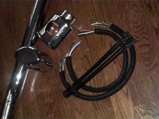
16 Inches of Extra Wiring
(Fig. B)The Orange Plug Serves as a Pin Lock Too
(Fig. C)
(Fig. D)They Just come Right Out
(Fig. E) The Stagger helps keep a large bulge from forming in your harness. Note the heat shrink tubing ready to be shrunk onto the bare wire.

 Please click here to visit my new site.