

I've been working on a home brew compass sensor design based on the Dinsmore 1655 Analog Compass part. This is my first attempt a home brew sensor.
Background
The goal was to make a compass sensor compatible with the RCX and have it only take one sensor input port to take a compass reading. We decided to use a Dinsmore analog compass part that has two outputs that need to be combined to determine the direction the compass is pointing.
With our design, it takes two readings by the RCX to get one complete reading from the compass sensor. Software then must combine those readings together to determine the angle the compass is pointing. We had to do it this way because of power demands by the Dinsmore part and power limitations of the RCX.
We wanted to add hardware around the Dinsmore sensor to combine the two outputs into one RCX input. We first tried to put all the "inside/outside crossings" logic into hardware, but we found out the hard way that the RCX can only provide about 10mA of current. It turns out we can only power 1/2 the Dinsmore compass sensor at a time.
Rick Sammartino (RickSam from the Mindstorms website) who has been helping me all along, had and idea of reading one curve then the other. This fit well with powering one compass sensor then the other.
Dinsmore Compass
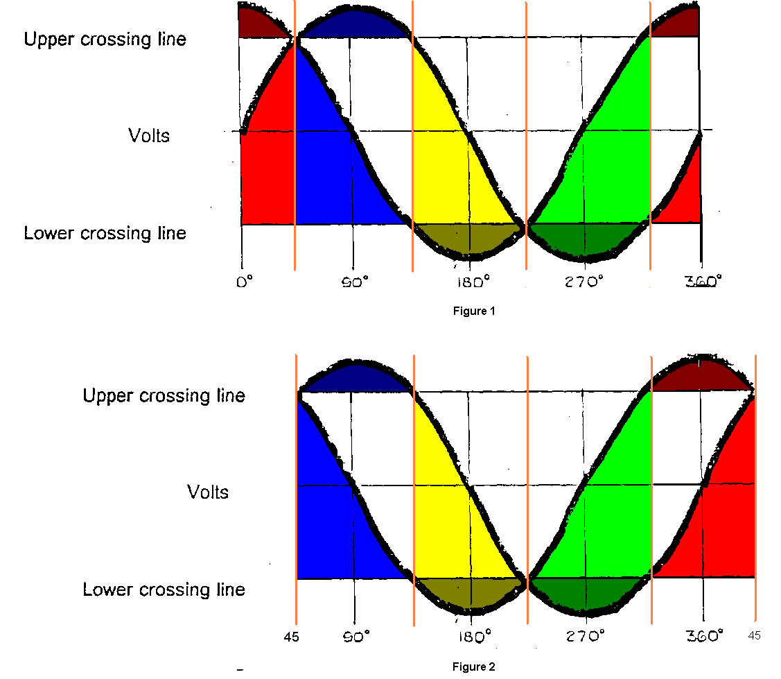
The Dinsmore compass sensor has two outputs that need to be combined to know the direction you are pointing. Figure 1 shows the compass outputs as they look across a 360 degree turn. It took me a while to make sense of the compass sensor outputs.
To determine the outputs' values when pointed a particular direction, draw a verticle line at the angle you want the compass to point. The vertical line intersects with the two output curves only once per vertical line. These intersections are the two output values you can expect when the compass is pointing in that direction. As you rotate the compass, you are basically sliding your vertical line left or right on the graph.
As you rotate the Dinsmore compass, there are two angles where the output values are the same. One is above the 2.5V center line, and the other is below the 2.5V center line. We'll call these the upper crossing and the lower crossing. Knowing these voltages are important to understanding the compass output.
At any given orientation, one of the Dinsmore compass outputs is either above the upper crossing, or below the lower crossing while the other compass output is between the crossings (unless you are at one of the two crossover points). The output that is between the crossings is follows a fairly straight line, while the output outside the crossings does not.
The trick is to determining the direction the compass is pointing is to determine which output is outside the crossings, and then use the output that is inside the crossings to know the angle.
The software for reading the compass is pretty compact.
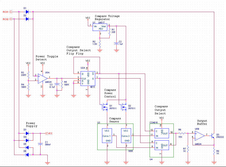
Schematic
We designed and debugged a "two reading" circuit shown in the schematic. The circuit has four major parts: RCX power supply, compass output select state machine, compass power and output select, and RCX sensor readings hardware.
RCX Power Supply
We get the power we need to run the electronics in our sensor by setting the RCX sensor port type to light sensor. This makes the RCX output 7 volts at a maximum of about 10 mA of current. Every 3 milliseconds the RCX drops the power for about 1/10 of a millisecond to take a sensor reading.
The cables that connect sensors to RCX sensor inputs can be oriented one of two ways: cable pointing towards the IR port, or away from the RCX port. There are two terminals on an RCX sensor port. The RCX always sends power out one terminal and back in on the other terminal. When we connect a sensor with the cable pointing toward the RCX's IR port, the power travels down one wire and comes back the other. When we orient the cable the other way, the power flow is reversed. Reversing the power can be bad for electronics, and they certainly won't work as planned.
To allow the user to connect their sensor cable with either orientation we use something called a diode bridge to make sure the power always flows the correct direction. A diode bridge is make up of 4 diodes. In our schematic, diodes D3, D4, D5 and D6 form the diode bridge. A diode is an electronic device that only allows power to flow one direction. It is similar to a "back stop valve" in plumbing that only allows water to flow one direction through a pipe.
When the sensor cable is hooked to the sensor input with one orientation, power travels into our circuit through D3, and back to the RCX through D6. With the cable the other way, power travels in through D4, and back through D5. The ends of D3 and D4 that are hooked together always provide the power, and the ends of D5 and D6 that are hooked together always return the power.
As mentioned before, every 3 milliseconds the RCX turns off the 7 volt power to the sensor to take a reading for 1/10th of a millisecond. This means that our electronics are unpowered during that 1/10th of a second time period. 1/10th of a millisecond (1/1000th of a second) may seem fast to us humans, but this is pretty slow in electronics terms, so we need a way to save up some power to run the electronics while the power is off. We use a capacitor C1 to store up power for these power out periods.
A capacitor acts like a water tower. It has pumps that fill it up, but it takes time. As the tower fills up with water it gains energy, because gravity pulls down on the water. As people use the water, the gravity pulls the water down and into their houses.
Capacitors work in much the same way. While the RCX is sending power to our sensor, the other electronics in the sensor use the power, and capacitor C1 charges up until it is full. When the RCX shuts off the power, the rest of the electronics draws its power from capacitor C1. The electronics can function normally until capacitor C1 runs out of power.
The size of the capacitor (measured in farads) you use depends on how much power you need and for how long a time. The larger the capacitor, the longer it can survive a power outage. We need our electronics to survive longer than the 1/10th of a millisecond power outages.
Our sensor needs to provide two different readings to software in the RCX to know what direction we're pointing. This means the software needs to tell our sensor to stop reading one compass output, and start reading the other compass output. The software signals this to our sensor by turning off the power for a longer period of time. We need the electronics to stay alive over this longer period of time so it can remember which compass output it is currently on.
These power outages can last in the 10 to 20 millisecond range. Capacitor C3 is large enough to provide power to the other electronics for this long a power outage.
The 7V power provided by our power supply is called VCC (everything has to have a name ;-). The place where the power returns to the RCX is called ground. In electronics ground has its own special symbol that looks like a triangle pointing down mad up of horizontal lines. Since our sensor is a rather complicated RCX sensor we do not run lines all over the page showing power and ground hookups. Instead we show local hookups using VCC and ground. You just have to imagine that there are wires (lines) leading from the power supply to the various electronic components.
The Dinsmore compass needs to have its power very stable to give reliable readings. We use an LM317 voltage regulator U1 to provide the same voltage to the Dismore compass, even if the power from the RCX fluctuates. The voltage regulator and its companion resistors and capacitor provide 4.5 volts (4.5V) to the Dinsmore compass. The Dinsmore compass is supposed to run on 5V, but the RCX cannot provide enough power at that voltage, so we run the Dinsmore compass at 4.5V to save power.
Compass Output Select State Machine
Our sensor and the software need to always be in sync about which compass reading is being sent by the hardware, and which reading the software is receiving. Our sensor remembers which reading it is currently sending using a digital memory element called a flip flop.
In the schematic the flip flop is component U2A. Our flip flop has 5 inputs and two outputs. The two most important inputs are the D input and the CLK input. These two inputs work together. The D input is for inputting data. The CLK is a clock input, which is used to tell the flip flop "forget what you were remembering and remember what is on the data input."
The Q output is the value that the flip flop is remembering. The NOT Q (a Q with a bar over it) is the opposite of the value being remembered. If Q is outputing a 0, then NOT Q is outputing a 1. If Q is outputing a 1, NOT Q is outputing a 0.
The two remaining inputs S (for set) and R (for reset) can be used to force the flip flop to either a 1 or a 0, without having to put the value on the data input and clocking it into the flip flop. We do not use these in our sensor.
The flip flop is used to remember which compass output we are sending to the RCX. Each time the RCX tells us to switch to the other compass output, the flip flop needs to change to the opposite of the value it currently has. If it is currently remembering a 0, it needs to remember a 1. If it is currently remembering a 1, it needs to remember a 0. The NOT Q output is the opposite of the currently remembered value, so we hook the NOT Q output to the data input. When we apply the remember clock, the flip flop changes value.
The software in the RCX turns power off, and then on to tell the flip flop to change its value. We use operational amplifier U5C and some resistors and capacitors to detect power toggling (being turned off and on.)
To amplify is to make something larger from something smaller. Your car stereo has an amplifier in it that makes the small radio waves, or small magnetic changes on tape large enough to wiggle speakers so we can hear it. How much you amplify something is called gain.
An operational amplifier (op amp for short) is a general purpose electronic amplifier that is easy to use. It has two inputs and one output. An op amp subtracts one of its inputs from the other and sends an amplified version of the difference to it's output. An operational amplifier has very high gain, which means it can take small differences nad make them very, very large. We can control the gain of an operational amplifier by adding or subtracing some of the output from the input.
We use an LM324 quad operational amplifier chip in our schematic. It has four operational amplifiers on one chip that all run off the same power supply.
So how do we use an operational amplifier to detect power toggling? First we must think back to the power supply explanation. The power supply uses diodes to make the power from the RCX travel in the correct direction, and we use a capacitor to store power for power outages.
To detect power outages we use a second pair of diodes D1 and D2, that act just like diodes D3 and D4. Power comes in D1 or D2, and goes out D5 or D6. In this case though we do not use a capacitor to cover for power outages. This means that the power coming through D1 and D2 goes on and off when the RCX turns power on and off.
The flip flop remembers new values when the clock input goes from a 0 (no power) to a 1 (power). It is called an edge triggered input. The change from a 0 to a 1 has to be fast for the flip flop to notice it. The RCX's change from no power to power is too slow for the flip flop to notice. To make a faster rising change, we use the subtracting nature of an operational amplifier and it's ability to change values very quickly, by using the op amp's maximum gain.
We run the voltage from D1/D2 to the positive input (pin 10) of U5C. We run a reference voltage (one that does not change) to the negative input (pin 9) of U5C. The operational amplifier subtracts the refernce voltage from the D1/D2 voltage. When the reference voltage is larger than the D1/D2 voltage, the op amp puts out a very low voltage (almost 0V). When the D1/D2 voltage is larger than the reference, the op amp puts out it's maximum voltage. As the D1/D2 voltage goes from lower than the reference to even just a little bit higher than the reference voltage, the op amp output voltage rapidly goes to its maximum output voltage because we are using the op amps maximum amplification capabilities. Using an op amp with its maximum gain like this is called a voltage comparator.
Using U5C as a voltage comparator makes our power toggle detect signal rise fast enough to clock the flip flop.
We generate the voltage reference by using two resistors. Resistors are electronic components that resist the flow of electricity. In resisting the electical flow power is lost through the form of heat. When the power is lost, there is voltage from one end of the resistor to the other. This loss is called a voltage drop.
We want our voltage reference to be somewhere between 0V (the lowest voltage) and 7V (out highest voltage). To do this, we our 7V from our power supply into one end of a resistor, and we hook the other end of the resistor to ground (0V). The incoming voltage stays at 7V, and the outgoing voltage stays at 0V, so there is a 7V drop across the two resistors. The voltage where the resistors meet in the middle is based on resistive the two resistors are. If the two resistors are of equal resistance (measured in ohms), half the voltage drop is due to the first resistor and half due to the second, so the voltage in the middle is 3.5V.
Our reference voltage for power toggle detect is generated using a voltage divider implemented by resistors R3 and R4. The middle voltage in our divider is 7V (VCC) * 100,000 (R3's resistance) / (100,000 (R3's resistance) + 220,000 (R4's resistance)) or 2.1V. This voltage reference is used again for other purposes.
Compass Power Control
The Dinsmore compass is actually two sensors in one. Each sensor has its own power connections, so we can power each one seperately. To satisfy RCX power limit constrainst we can only power one half of the Dinsmore part at a time. When one half is powered, the other half has to be unpowered. In electronics we can use transistors to turn things on and off. We use two MOSFET transistors to control the power to each half of the Dinsmore compass. MOSFET transistors are very good for controlling power because they consume very little of the power they control. Power goes into a MOSFET transistor in the source input. Power traveling though the transistor is controlled by the gate input. The power comes out of the MOSFET through the drain output.
In our sensor, the source power is provided by U1, the Compass Voltage Regulator. The drain output is connected to a half of the Dinsmore compass to deliver power (or not ;^) The gate inputs of our two MOSFET transistors are controlled by by our Compass Output Select State Machine flip flop. Remember that our flip flop has two outputs Q and NOT Q, and that NOT Q always has the opposite value from Q. So if Q is on, NOT Q is off and visa versa.
This sounds exactly like the way we need the power delivered to the two halves of the Dinsmore compass. We hook Q to the gate of one of our MOSFETS, and NOT Q to the gate of our other MOSFET and only one half of the Dinsmore compass is powered at a time.
Compass Output Select
Each Dinsmore compass output is a voltage that varies based on the direction the compass is pointing. Unlike our digital flip flop who's output voltages can only have two values either on (high voltage) or off (low voltages), the Dinsmore compass is analog which means a whole range of voltages.
The Dinsmore has two analog output voltages, and we have to choose one of them to send to the RCX. Electronics provides us with a wonderful thing called an analog switch for just this purpose. An analog switch has two inputs, and an output. One of the inputs is called the control. When the control input is driven so the switch is on, the analog input is sent to the analog output. If the control input is driven to turn the switch off, the analog output is disconnected from the analog input.
We use two analog switches to route the Dinsmore compass outputs to the RCX. There is one analog switch for each compass output. We connect the Q and NOT Q outputs from our flip flop to the control signals on our two analog switches. We also hook together the outputs of the analog switches which is sent off to the RCX. When Q is on, it turns on a MOSFET that powers one half of the Dinsmore compass. The output of that half of the compass is fed into an analog switch, who is also controlled by Q, so the output is fed onto the RCX.
When Q is off, NOT Q is on, so the other MOSFET is turned on, the other half of the Dinsmore compass is powered, and the other analog switch is turned on, so the second compass output is fed to the RCX.
We're most of the way through our sensor explanation, so I hope you are still with us.
Final Output Stage
The remaining part of our sensor feeds our selected output to the RCX.
The Dinsmore compass output gives us less than one degree of resolution. Resolution refers to how big or small the smallest detectable part is.
The Dinsmore part can only provide 4mA of current. To make sure we do not draw too much power through the compass, we run the selected compass output through an operational amplifier that interfaces to the RCX. This guarantess that we don't draw too much power. It also allows us to better interface to the RCX's resistance based sensor reading technque.
Diodes D1 and D2 combined with D5 and D6 are how the RCX actually reads the sensor values. The RCX sends a small amount of power through either D1 or D2, our operational amplifier combined with a 2N2222 transistor only lets some of that through and back to the RCX through either D5 or D6.
Here is a calibration program that determines required delays and crossovers readings. The prototype compass software provides us better than 1 degree angular resolution.
I have not had a chance to perform accuracy measurements. I will add a rotation sensor to my rotating test bed and perform accuracy measurements. The software can be modified to compensate for some inaccuracies.
