Beomaster 4400 (+ Beocenter 7000)

That year's top-line B&O tuner amp, this was based on a well-used design that gave service, with only a little modification, in many models and, a favourite though occasionally cranky, the remote-controlled Beocenter 7000 (type 1801, shown at the bottom of this page) mainly differing in this type by mounting two output pairs in series, thus decreasing dissipation in the individual output devices and increasing the safe operating area, say, for capacitive loads.

Most variants involved changes to the input pair's constant current source and the addition of small capacitors, the major changes seen during the production of the quadrophonic Beomaster 3400 (type 2802, from s/no 142044).
Considerable attention was paid to feedback paths, the Cbc of the class A driver being important. An RC network (47p + 56R) ties the base of the class A driver to the output. By including the output stage in the feedback reduces crossover distortion considerably. Earlier variants indicated stability problems (MPSH54 in this version, BC547B et al in earlier types). Replacement with an incorrect value could result in RF oscillation and an amplifier burn out. As a stock fault the sensor transistor (BD135) mounted on the heat-sink would open-circuit. Checking the RC output load with any fault proved a good idea, faulty components then replaced with upgraded ratings. It is felt that the 47µF cap (5C138) decoupling the feedback was similarly under-rated, this necessitating replacement in the event of an output short to a supply rail.
Apart from current-limiting the output, feeds were taken from the outputs to a DC sensor together with the output of a PTC thermistor mounted on the heat-sink. Upon operation, a relay cut the DC (post-smoothers) supply lines.

To prevent TID the input was fed via an active 20kHz Bessel filter (-3dB @ 50kHz), after a mute FET intended to ground the signal under input switching and power up/down conditions. The collectors of the 'specially selected' input pair were connected via diodes to an overload indicator, any differences between the inputs (distortion) then indicated by a bulb with a prolonged 'on' time for short duration events.

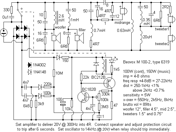
Delivering about 75W, matching speakers would be the Beovox M 100-2, which also contained protection circuitry (below).

On a personal note, it was felt that B&O's insistence on using 4R loads as a standard detracted from efforts made elsewhere in their designs. DIN standard connectors could disappoint.
One system (4400 + M100) was fed, via a specified matching transformer, from that year's topline Beovision. From new, the owner complained of reduced output from the TV. Intense examination showed that everything checked out, until an inspired guess showed that the IF IC (TBA120) in the TV was a low-gain, and thus out-of-spec device. Up to this point, an additional gain stage had even been considered.
The tuner in the 4400 could also interest. A bulb-saving circuit, intended to increase indicator life by 40%, would on bulb-failure mute the tuner. Another stock fault in the tuner head (C9, 8p2) would result in oscillator failure on warm-up. As with other B&O products, one symptom then might have a number of causes.
Ambitious design, overly complex systems that interact, and attempting to increase reliability by increasing the component count, especially if commercial grade is used, can be a false economy. Despite B&O having a true expert at the end of the phone when needed (and if you've never worked on B&O, you won't know what I mean), quite baffling and time-consuming faults were often found to be caused by apparently completely unrelated components. One TV, the Beovision 3500, employed 2 EHT stages, instead of the usual 1. This complex design (although praised for it's external appearance) was abandoned with very good reason. The same could be said for the Beocord 5000. Some B&O tuner-amps had a fashion of blowing their mains fuses by shorting the transformer secondary with a triac, under fault conditions. Later modifications recommended removing this altogether, and again with good reason, the trigger circuit being far too sensitive. An intermittent computer fault in a relatively new (2 years) and very nice remotely-controlled Beocenter 7000 left the author's and B&O's service departments at a complete loss, since no replacement was available.
Power amplifier for Beocenter 7000

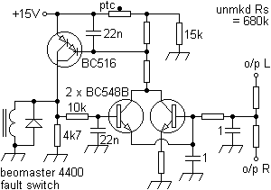
and the fault switch for same which, on operation (overcurrent through output device's emitter resistors), grounded a 4.6Vpk half-cycle AC signal (mains detect) from the supply to the system's microprocessor (µC8048) which in turn tripped a standby circuit that cut the high current (22-0-22V) transformer secondary with a relay, the mute (MPSA16) then activated via a comparator from the - side of it's coil.

Compare to earlier models.
especially if you want additional content to this page
or if you find any links that don't work. Don't forget
to add the page title or URL. Take care!