

Credit for images to William Beaty
Last week, I was accidentally responsible for what I believe to be the electrogravitic effect seen in the reports of the Gravity Capacitor. I had thrown away many layers I had made because they had either fallen apart or I was angry because they seemed substandard. I therefore took the remaining layers, of which there were ten, and finished insulating them by applying an underlayer of black polyethylene. I did not expect them to work, but I aligned them anyway, with the negative charging tabs about 90 degrees separated from the positive. Here are my results:
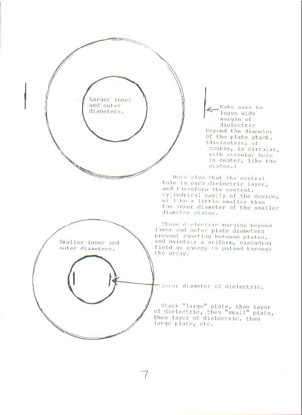
With a pair of compasses on paper, draw a circle of radius 63mm. Using the same central point, draw another circle 80mm in radius, and another 27mm in radius. The outer circle is the dielectric radius. The middle is the metal plate radius, and the inner is the "hole" radius. You will note that these are the same as used by the mysterious "S" in his experiments. This being done, use a protractor to divide the circles into nine segments. Draw another circle with the compasses, of radius 55mm, from the same central point, to delineate where the slots in the plates will finish.
Carefully mark a parallel line next to each of your segment lines, and on both sides, to show how wide the slots will be. On each side, these parallel lines should be 3mm from the segment line. Finally, decide which plate will house the tab, and draw this in. I made my tabs 60mm long, but you may wiah to vary this.
When this is done, photocopy the paper as many times as needed to produce more layers. Cut yourself, from cardboard, a template for the small wedge-shaped foil plates which will be glued to the paper. You cannot simply cut foil with scissors, as it will become badly mashed into itself. Instead, cut a long strip of foil, and one of newspaper, then concertina them together nine times, leaving a newspaper layer on the top. Draw around your plate template on this, then cut with scissors. You will easily produce nine identical plates like this.
Glue them to your photocopied paper design. I used UHU all-purpose adhesive, but I don't know if this is important. For linking the wedges, cut a thin strip of foil and divide into nine pieces. Using the same glue, use these small rectangles to bridge the gaps between the wedges.
Repeat this process to produce ten plates, then glue each piece of paper to a flat sheet of polyethylene and cut out the hole and the periphery of the plate. You should end with a finished composite plate, with plastic on the bottom, paper in the middle, and aluminium on the top.
The layers were carefully aligned so the wedges matched up, and were organised so there charges would be sandwiched between one another. I placed the whole thing inside a hardbacked book (student cookbook!), and bound it with an elastic band to keep up the pressure. The weight of the plates was 6 grams, the book 202 grams, and the elastic 2 grams, making a total of 210 grams. Placing it on my balance, I connected the tabs, which were protuding from the side of the book, to MINIMAX2 from Information Unlimited, via 2 metres of wire. The wires were separated to prevent static interference. The power was applied...............
I came across a small newspaper article, obviously a minor column blown up to huge size. This is important because it states that the lift of Doyle's GC was only a few grams. Perhaps he just built a GC, got it "wrong" but still experienced Biefeld-Brown type electrogravitic thrust. What we might condsider a failure was an amazing success to someone who had never heard of electrogravity before. This is startling too. If Brown electrogravity works on a "useless" GC, then is the GC powered by something other than electrogravity? This is even juicier, in that judging by the text, it seems like simply a Brown Gravitator. The picture (not here yet!) shows a crude GC however. How many "Brown" electrograv experiments which have only been written up and not illustrated are actually accounts of this device then? Judge for yourselves:
By Leif Sollid
Doyle's Law of Anti-Gravity is not to be found in science textbooks, nor
is it pondered over by professors and scientists.
In fact it doesn't even exist.
But if one highly-inventive and equally-determined Calgary high school
student's dream comes true, Doyle's Law may be one day more than just a
theory.
Although the initial idea for the project was not his own, he has worked
by himself on this and a similar project for 2.5 years.
But Buehler doesn't give up easily. He plans to continue experimenting,
gathering the evidence necessary to support the theory that electricity,
magnetism and gravity can be joined to "unify the field,"
He says money to continue his project is a problem. So far he has spent
more than $1000 on equipment, supplies and books and he needs more. He
would like to build a plexiglas vacuum chamber to conduct further, more
advanced tests.
His plans for the future?
"I could become a mad scientist and do this for the rest of my life," he
quips. But if he fails to prove the theory in a reasonable amount of
time, he aspires to be an astronaut, or at least an aerospace
engineer.The Set-up
I have a delicate analogue kitchen balance (used for dieters to easuer precise food quantities) which is accurate to 1/2 gram. I had previously glued the Gravity Cap layers to a polyethylene undersheet with UHU all-purpose adhesive. The plastic sheet was unfolded - only one layer thick. I stacked them up in a positve-negative-positive-negative fashion. Sketches of the plates will be coming soon, but here are the dimensions and the means of contruction:The Results
When the power was applied, the weight of the book dropped from 210 grams to 205 grams, a loss in the region of 2.5 percent. The loss remained after power was turned off, gradually tailing off to nothing over a period of 22 seconds. The Conclusion
It seems this device really does work! I am very enthused by this and will continue to experiment. However - cutting more than 15 plates will break your heart, in terms of time and effort. Could anyone get a few thousand of these stamped for me?Some old messages from FreeNRG-L, which may be of use to experimenters
What if it all goes wrong.......
Click here to view the diary!
Diary Updated 25/10/2000
Article from the Calgary Mirror, May 15, 1986
The student-scientist is Doyle Buehler, a Grade 11 Bishop Carroll High
School student and a competitor at the National Youth Science Fair at
the U of C (University of Calgary? - JB), May 10-18.
Buehler's project of antigravity, which won the top senior award at this
year's Calgary Youth Science Fair has uncovered a mysterious and as yet
inexplicable force.
When he sends an electrical charge up to 100,000 volts through his
homemade capacitor - two parallel plates - the whole apparatus
rises.
"It doeasn't actually lift off the scale," explains Buehler, "but it
does become three or four grams lighter - a significant amount."
"It is something external that makes it move" he says. But he and
everyone else remain mystified as to what the force is.
"I have spoken to a lot of people and they say it should not work. This
contradicts Coulomb's Law of Electromagnetism," he says.
He has received encouragement from a professor from the University of
Regina, who is conducting similar experiments. But, because his reults
are so contradictory to the established laws of science, he says school
teachers have not been much help.
"Basically, help from teachers has been what laws it (his project)
should be following, not what it is doing."
"I do not have enough sustained evidence to support it fully (the
theory), but I do have more plans on the drawing board."
Although he's hesitant to predict possible uses for the theory should it
ever be proven, he believes the implications are enormous.
"If we could tap that energy, we could have energy for trillions and
trillions of years. After we unify the field, we will understand our
universe....we could possibly travel to the stars."
A veteran of four science fairs, Buehler says he participates out of
interest and because of a yearning to "delve into the unknown."
For now, though, Buehler has enough of a challenge facing him in the
25(?)th National Youth Science Fair.
Here are the links to the other remaining GC pictures I have. Please note - page four is missing! Click on the links below to display the relevant files:
The main Newspaper article headline
The Electric Rocket was, according to what we know, created by a "17-year-old tinkerer", back when John D Rockefeller was still CEO of Standard Oil (Now MOBIL). For those of you not familiar with the history of this wonderful device, see here for the lowdown on it. The linked page belongs to William "Bill" Beaty, who has conducted much of the best researches into it.
It is a stacked multiplate capacitor with multiple poles on each plate, which when energised to 1.8 kilovolts+ will levitate with great force. This has shades of Fran de Aquino's ELF device, without the harmful radiation, iron shield or high currents. The problem with the device is that many of the experimenters working on it have come up with frustrating negative results when they switch it on. Although once you have built it, you have a splendid HV capacitor, which could be used as a Tesla coil tank capacitor, with 600+ plates which must be specially cut, things can get pretty infuriating!
The original was made of waxed paper dielectric and tin plates, although some research has indicated that aluminium works, despite ideas to the contrary, and that Mylar or other plastics may boost dielectric performance [they should try polysulphide ;) ]. The main purpose of this page is not to attempt a replication, but to outline which seem to be the most crucial elements of a successful design.
There are a number of other considerations which need to be taken into account when considering the working of the machine. The most important one of these that I have come across so far is one which was pointed out to me "Cliff", one of the GC researchers who William Beaty was in touch with. The piece which details this information is in somewhat hazy English, but I have placed it there for the sake of everyone understanding and hopefully gaining a few new insights into the device:
"This capacitor does have one major and critical design problem that I have found to be a success or failure. The tabs lengths and the tabs connections. Using tin plates vers aluminuim plates do have an impact due to the thickness and using different dialetric material will also change thickness of a small group of 40 plates or so. Grouping may not be important but, if by chance the tabs are of equal in lengths and by connecting the tabs they are still equal in lengths, the device will NOT work. Tabs from power common source to plates are extremely critical. By "common source" I mean where the first tab and the external power source juction, here is the trick part." - "Cliff", GC researcher
This seems to explain that there is a necessary bias in the creation of the device whereby the lengths of the tabs to the plates from the power common is important. William Beaty recommended using low-value resistors instead of veriable tab lengths to make this work right, but 390 sequentially valued resistors would be a little expensive, so I would advocate making all tabs the same length and then trimming until the thrust appears. EHF signals emanating from the capacitor also cannot be ruled out. This will be expanded upon shortly........
As if things were not complicated enough already, it seems that the Gravity Capacitor comes in different types. Although it is open season as far as the plate material and dielectric type is concerned, there are considerable geometric differences in the GC which also need seeing to. I have encountered at least five distinct variations on the device, each of which I shall outline below:
I AM UPPING MY SECURITY AFTER THE MYSTERIOUS DISAPPEARANCE OF MY TEXT - OTHERS BEWARE - PERHAPS THIS DEVICE REALLY DOES HAVE SOMETHING TO HIDE AFTER ALL......
