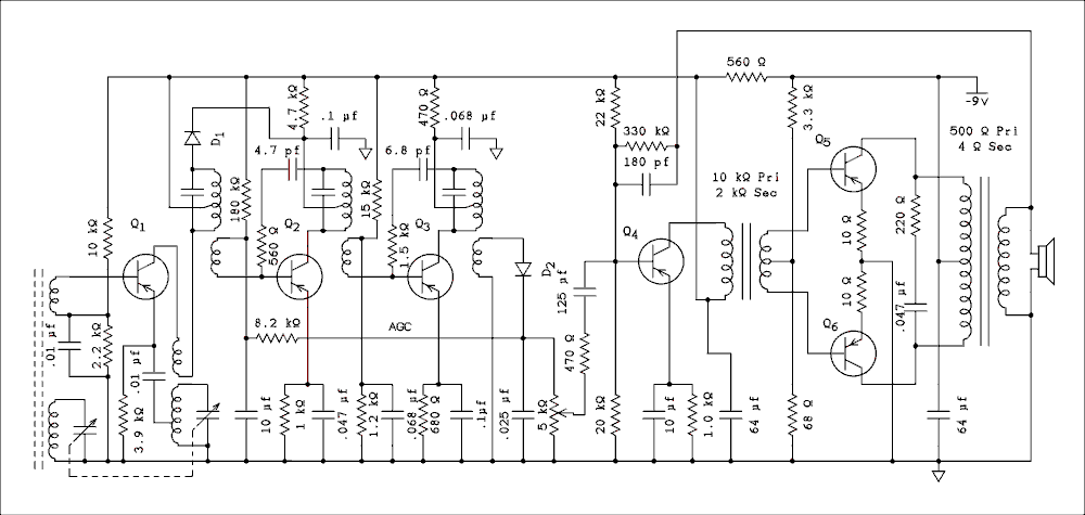
Voxson Model 762 Complete Circuit.
For a verbal description click here.
The All Japanese Six Radio.
The Audio Amplifier.
The first transistor in an All Japanese Six converts the frequency of the incoming station to the Intermediate Frequency (IF). After the conversion two transistors amplify the signal. The detector recovers the audio that was modulated onto the station's carrier. The audio passes through the volume control to the audio amplifier and then to the speaker.Here are the complete diagrams of the two AJ 6 radios we are studying.

Voxson Model 762 Complete Circuit.
For a verbal description click here.

Sanyo Super-Six Complete Circuit.
For a verbal description click here.
In the Voxson radio the signal at the wiper of the volume control is passed through a 470 ohm resistor then a 125 uf capacitor to the base of Q4. The input impedance at the base of Q4 is going to be a few hundred ohms due to the negative feedback but even if we consider a worst case of the capacitor with the 470 ohm resistor the lower corner frequency is 2.71 Hz. More likely this capacitor is supposed to be a 12.5 uf instead of a 125 uf capacitor. Let's describe the amplifier then come back to the negative feedback later.The base of Q4 is biased by the 22 k ohm and 20 k ohm resistors. The collector current is set by the 1 k ohm resistor in the emitter. The transformer primary is driven by the collector of the transistor. The other end of the primary connects to -9 volts which is bypassed to ground by a 64 uf capacitor. This capacitor in conjunction with the 560 ohm resistor decouples the collector supply for Q1 through Q4 from the collector supply for Q5 and Q6. The interstage audio transformer couples the audio from the collector of Q4 to the bases of Q5 and Q6. This transformer is an impedance stepdown which is also a voltage stepdown. However it is a current step up. Transistors are current devices so the transformer is actually providing gain along with the transistors.
The bases of Q5 and Q6 are biased by the 3.3 k ohm and 68 ohm resistors. The collector currents of Q5 and Q6 are set separately by the 10 ohm resistors in each emitter. These resistors in addition to providing thermal stabilization also compensate for mismatched transistors. And furthermore they introduce some negative feedback to improve the distortion figure of the amplifier.
The collectors of Q5 and Q6 connect to each end of the output transformer and the -9 volt supply goes to the center tap. The 0.047 uf capacitor and 220 ohm resistor provide frequency compensation to keep the amplifier from oscillating or ringing when feedback is applied. The secondary of the transformer drives a speaker and a headphone jack not shown. Negative feedback is taken from the secondary through a 330 k ohm resistor and a 180 pf capacitor back to the base of Q4.
There are only 5 differences between the Voxson and Sanyo circuits. 1) The signal is coupled from the volume control to the base of Q4 by a 10 uf capacitor only with no series resistor. 2) In the Q4 collector circuit there is a 0.005 uf capacitor across the primary of the audio interstage transformer. This capacitor along with the 10 k ohm primary impedance gives a corner frequency of 3.18 kHz. That seems a little low so once again we may have a case of an incorrect value on the schematic. 3) The emitters of Q5 and Q6 are tied together and go to ground through a single 10 ohm resistor. 4) There is only a capacitor across the primary of the output transformer. And 5) there is no negative feedback around the amplifier.
General Information.
The Converter.
The IF (Intermediate Frequency) Amplifier.
The Detector and AGC/AVC (Automatic Gain Control/Automatic Volume Control).
The Audio Amplifier Section.
Conclusion.
This page last updated April 25, 2011.