There have been a few changes since these videos were shot... mainly the installation of Swamp's Diesel Performance 250/173 injectors. I need to get some new videos. Tire fry action is MUCH improved now!!!!!
Videos
Truck video
Truck Repairs and Things
Turbo Rebuild
Here are all of the pieces laid out on the table.
Not sure what this is, or where it goes, but it was in the box on the bottom rolling around by itself.
Slowly piecing together the supplied kit making sure I know what everything is and where everything goes before I get started. Still trying to figure out where that fitting on the bottom center of this picture goes, and am also wondering if there is a way to go from the pump to a male -6AN style fitting. I'm thinking of not using the rubber lines and going with braided.
Fuel fitting tools ready to go.
12/18/06 - Buffing and Polishing a little bit
Trying out the buffing /polishing stuff on a piece of 4" stainless pipe for the air filter to clamp to.
White rouge 1x.
White rouge 2x.
Red rouge 1x.
Red rouge 2x.
Waxed and ready to go.
Intalled on the truck.
12/11/06 - Hi-Rev Valve Spring Installation
Valve springs have arrived. These reuse the stock rotators.
Here are the spring specs off of the side of the box.
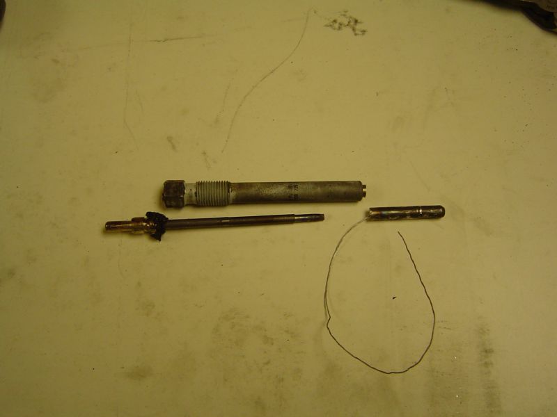
A glow plug was sacrificed and brutalized into three pieces.
The tip had to be drilled out. The center section twisted off inside of the housing.
We now have a flow through glow plug to attempt to flow compressed air through to hold the valve up during the spring installation.
The springs again, the glow plug Motorcraft ZD-11, and here is the Valve Squeeze Tool.
Here is the modified glow plug, about 4" of tubing, and an air fitting to be welded together.
All welded together. I was very careful to protect the threads of the glow plug. I have pin holes every where. I'm not a good welder anyway. The welds have to be strong enough to hold this contraption together, or I'll probably be fishing a valve out of the cylinder with a magnet.
JB Weld to the rescue to seal the pin holes. Hopefully, when I wake up I will have time to see if this actually works. Stay tuned...
It's tomorrow already. Here is the flow through glow plug and the valve squeeze tool in action.
Stock vs. Comp Cams 940-16 springs.
The new larger springs look like they hit the metal part that holds the injector down. I hope this doesn't turn into a future problem. Changing the valve springs is about as fun as the head stud installation - uuuuugh! That's right, I only have three cylinders done so far.
Rockers, glow plugs, and some pushrods removed to make the job a little easier. The AC condensor cover will still need to be removed to change the rear passenger side springs.
I almost forgot the star of the show. This little telescopic magnet made life easy removing the retaining clips from the valve and reinstalling them.
I had to remove the AC cover to get the rear most passenger side spring. I must mention the driver side was much easier! This job ended up mot being anywhere near as much work at installing the head studs once I got a rythm going.
Some of the tools used to install the new valve springs.
11/26/06 - Headstud installation
I didn't follow the torque specs very well. Since I wasn't changing the head gaskets, I removed one head bolt, then installed one head stud following the step 1 numerical sequence. I torqued step 1 to 90 ft-lbs, step 2 to 115 ft-lbs, and step 3 to 125 ft-lbs. I also used molysulfite on the threads so I guess the actual final torque ended up closer to 139 using the 10% rule. The 10% rule is you subtract 10% from the final torque when moly is used. My spec was 130 ft-lbs, so I went a little over. I guess I should have calculated before I did the final torque. It's done now and I'm not going to loosen them.
Top to bottom: Here is the protective tube the stud was shipped in, molysulfide in IPA solution, head bolt, head stud, nut and washer.
Head stud installation is not a fun task! Here the passenger side has been completed and the driver side fun is about to begin.
Here are some of the tools I used.
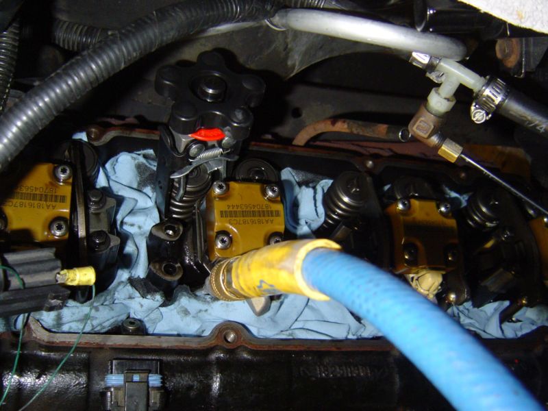
This vacuum pump was very handy. It has a catch can (jar) to collect the oil being pumped out of the injector area.
In the ccenter of this picture you can see the small hose from the vacuum pump going into the injector's opening in the head. Not shown is the rear most head bolt. A hole can be cut into the firewall, or the cab tilted to the side. I opted to tilt the cab.
The injectors are removed. I have a set of Swamp's Diesel Performance 250/173 injectors and their latest 6 page chip for these injectors as of 11/9/2006. The next series of pictures shows what is involved with tilting the cab to remove that rear most driver side head bolt.
The front cab mount bolt is removed from under the passenger side of the truck.
The rear seat had to be removed to gain access to the rear most cab bolt on the passenger side.
The passenger carpet must be pulled back to gain access to the plug in the floor that reveals the hidden bolt head that comes up through this hole.
A floor jack and some blocks of wood are used to jack up the passenger side of the cab to gain room on the driver side rear head bolt. It is a good idea to screw the blocks of wood together.
this is how much I had to tile the cab. Make sure the fan shroud is hanging loose. You don't want to risk bending a fan blade or ruining a different part of the truck. This job is tough enough with out self inflicted wounds... and yes, the cab needed to be lifted each time to get the socket and torque wrench on that rear most head stud.
Think you are done with the problem areas? Guess again! the driver side front most head bolt will not clear the power steering pump.
I had to back the power steering pump mounting screws out until they touched the pully to make enough room to remove the head bolt and install the head stud.
Ahhhh, the head stud is installed. Do not tighten that power steering mounting back up until the stud have been torqued for the final time. It makes life much easier that way.
All back together. some things not noted but need to be mentioned. I had to peel the rear heat shielding away from the firewall to help gain access for the rear most driver side head bolt. On the passenger side, I had to split the AC condenser cover and remove the inner panel to make room for the rear most passenger head bolt. I did not put the heat shield material back on the cover once reinstalled. I hope this in not a problem in the future.
Oh yea, remember that nifty trick of turning the engine over with the injectors removed to get rid of the residual oil that goes into the cylinders? I laid a towel over the openings to the oil would not make a mess. The oil comes out of the injector hole with such velocity it goes right through the towel and splatters everything including the wall behind the truck - see the background. There was oil everywhere that added at least 30 mins of clean up to the job. I shouldn't have gotten lazy with the vacuum pump. In edit: to avoid the risk of bending a rod, always turn the engine over by hand a few rotations first. It is easier than you think (at least with an auto, not sure about the manual). Remove the flexplate cover, put on some work gloves and start turning. Watch for the torque convertor drain plug to come around a couple of times.
CB
CB mounted.
CB antenna mount. This is on the driver side fender since 1997. No holes need to be drilled.
Exhaust is 1.0 A/R turbine housing, gutted EBP valve housing (welded shut and lightly ported), Banks 3" round downpipe, 3 1/2" straight pipe exhaust w/4" chrome tip (Banks mandrel bent tailpipe), 4" rear spring blocks out of an F-350, rear tire wear with some recent burnouts.
97 Powerstroke
Transfer Flow Front tank
Transfer Flow Rear tank
You can see how far the spare has to be dropped.
Here is a link to the MAP Simulator Circuit.
This is Asmith's circuit, and the link is 95Deezel's.
This is why you don't want a 17" long line (measured from o-ring to o-ring). Imagine trying to replace the fuel filter/water separator.
NOTE: I have since installed a 20" long line and no rubbing at all. No split piece of rubber protecting against rubbing was needed either. The fuel filter servicing is not hindered anymore either.
K&N filter set-up with Stainless coupling
Let me tell you about my truck
- This is the first and only vehicle I bought new.
- In 1997, this was not a common color (Saddle Clearcoat Metallic)
- It shifts like garbage. (E4OD automatic w/TDE1 program)
- It was tough to fit the whole truck in the picture with out being a mile away.
Web Sites
Home
Swamp's Diesel Performance
www.thedieselstop 94-97 forums I post on sometimes.
I post as "Mick" there #371. That's not accurate since I had to re-register in April of 1999. I have been a member of these forums back in July of 1997 when thedieselstop used to be called Jason's Powerstroke Page, prior to www.ford-diesel.com. Just a little history there.
I hope to get a few hundred thousand miles out of this truck.

E-mail