Site hosted by Angelfire.com: Build your free website today!


Phil's Tube Amp Project

[April 7, 2004]

A number of months ago I stumbled across a web site that was geared towards homemade tube amp construction and I decided that I had to try my hand at it someday.  A basic design called the "P1" is presented and various enhanced versions have been built and detailed on this web site.  The web site is called the AX84 Project (ax84 home link).  The version I chose to build is called the "High-Octane" which is a P1 design with additional pre-amp stages (high-octane home link).  This web page is my commentary on how I am building this amp.  I am not diverging any from the planned design, although I am using the parts that are the most readily available to me and have made a few decisions along the way in areas that are left up to interpretation.  The high-octane web link has a number of images and sound clips from others who have built this same amp.  Mine will be a single unit with the component chassis mounted upside down and inside the cabinet, hanging from the top.

I soon began collecting parts when I could find them on ebay.  The first part I bought was the speaker, a 10" Jensen C10Q model.  Later I came across auctions for the power transformer and the output transformer and added them to my parts collection.  At that point I had all the most expensive parts to build the amp.  Most of the regular electronic components were purchased online from Mouser Electronics and I did buy other parts online from a couple of vendors that deal in parts for amp construction and repair.  The tubes and chassis were ebay purchases also.


This is my collection of parts prior to beginning construction...


This is the schematic diagram I am working from to build this amp...


The following link provides better deatil of the schematic along with the original bill of material that I started with...

high-octane schematic pdf file


[April 9, 2004]

I have relied heavily on the information found at this web address:

http://silvatone.bravepages.com/HO/HOIndex.htm

This site has a parts list with part numbers listed, which saves quite a bit of time looking up components in online catalogs.  It also pointed me to a couple of other sources to go to looking for parts.  Another place I ordered from was Ampwares which is the only place I could find that carried spring retainers for both types of tubes I would be using.  I wanted spring retainers to hold the tubes in the sockets because the chassis would be mounted upside down in the cabinet.

Parts List
Follow this link to see the complete parts list to date.  I have bought parts from various sources, most notably Mouser Electronics.  They will sell most components in quantities of one, which is nice that you don't have to pay for extra parts you won't use just to get one or two.  They were backordered on some parts and when it came time for those to be shipped I canceled the backordered parts because they totaled less than $2 and were going to charge $5-$7 for shipping.  I bought them locally for just over $2.

[April 13, 2004]

The first step in the actual construction was to cut the plate for the front panel and drill the holes for the knobs, switches, lamp, and jack.  I used a 2" wide piece of 1/8" steel plate that I bought from a local hardware store.  Aluminum would have been lighter and easier to cut and drill, but steel was cheaper.  The holes were drilled with small bits to get the holes started, then I switched to something called a "unibit".  I have never used one of these before.  It is a single drill bit with a graduated diameter, incrementing in steps of about 1/16".  It worked great.  I was also able to turn the plate over and drill from the back side to de-burr the holes, leaving a clean finish on both sides.


Before cutting the chassis, I wanted to get the layout of all components completed.  This has been the most difficult step of the project so far.  I had to come up with a layout that would work for the size chassis that I bought for the project.  This is the first cut of the layout I generated and the final version I did on a true-size grid:


It has been checked out a couple of times against the schematic to make sure I have no wiring errors on this diagram that I am building to.

The next step was to make the cutouts in the chassis.  I laid out the following diagrams to use for a cutting guide:


I printed these and taped them directly to the chassis.  It looked like this when finished before it was cleaned up:


After I filed the chassis holes clean I installed the mounted components:


[April 15, 2004]

I finally got around to wiring the components in the chassis.  I got about halfway done with it this past weekend.  Here's what it looks like so far:


The main thing I wanted to accomplish at first was to get the power supply connected and tested out.  I did my first power-up without the tubes installed to see if my power indicator light would come on, and it did (without smoke and bad popping noises that let you know that you are probably finished with a 
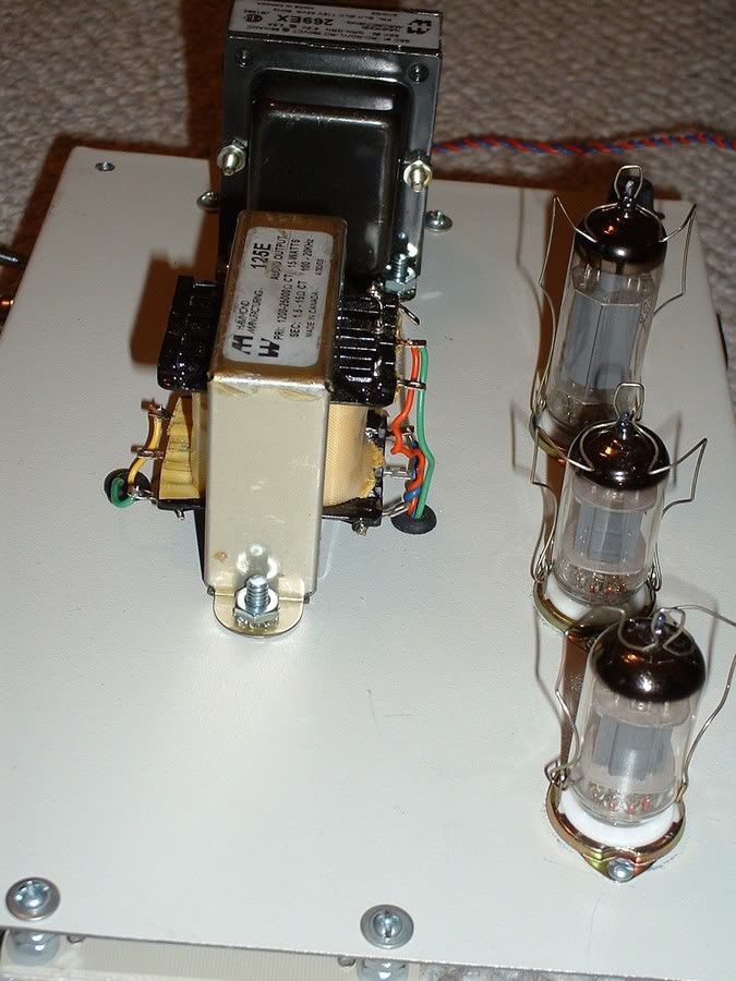
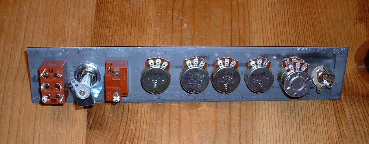
project such as this).  I double-checked the connections to the tube sockets and checked the filament voltages before installing the 
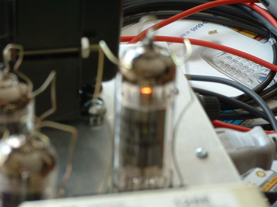
tubes.  I wanted to see that warm orange glow from the tube 
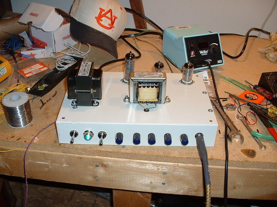
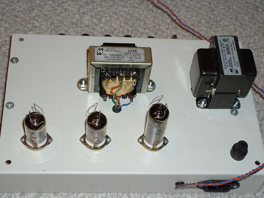
filaments, so I popped them all in their sockets.  The filament in the power amp tube began to glow (see the out of focus picture) but the pre-amp tubes did not have the same visible glow, but they did get warm.  I don't know if I should be able to see the filament in those tubes, but I was satisfied that they did get warm at the 
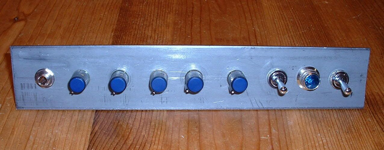
top.  At the time I took these pictures I did not have any of the signal lines connected to the tube sockets.


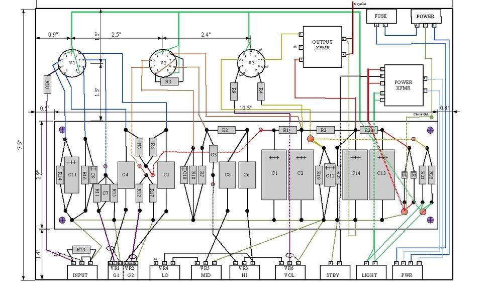
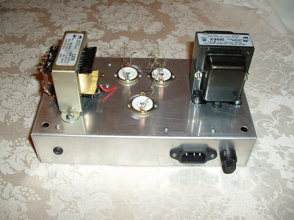
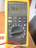
The power transformer has two outputs on it.  One is rated at 6.3V which powers the indicator lamp and 
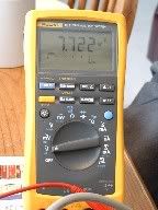
the filaments only.  The other is a 190V output, but what is shown on the meter below is the AC measurement between primary taps.  This is about the no-load AC range I expect.  The no-load DC measurement at the power supply filter output measures about 213V.  So far it looks good.  I hope to finish the chassis wiring this coming weekend to pump some sound through it for the first time.


[April 29, 2004]
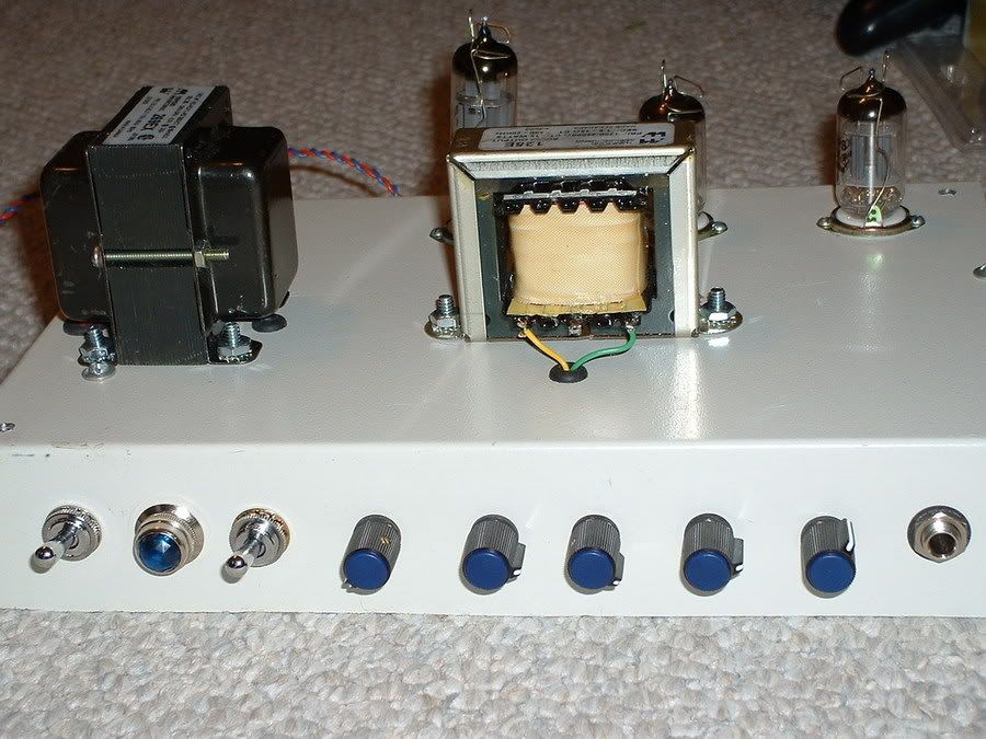
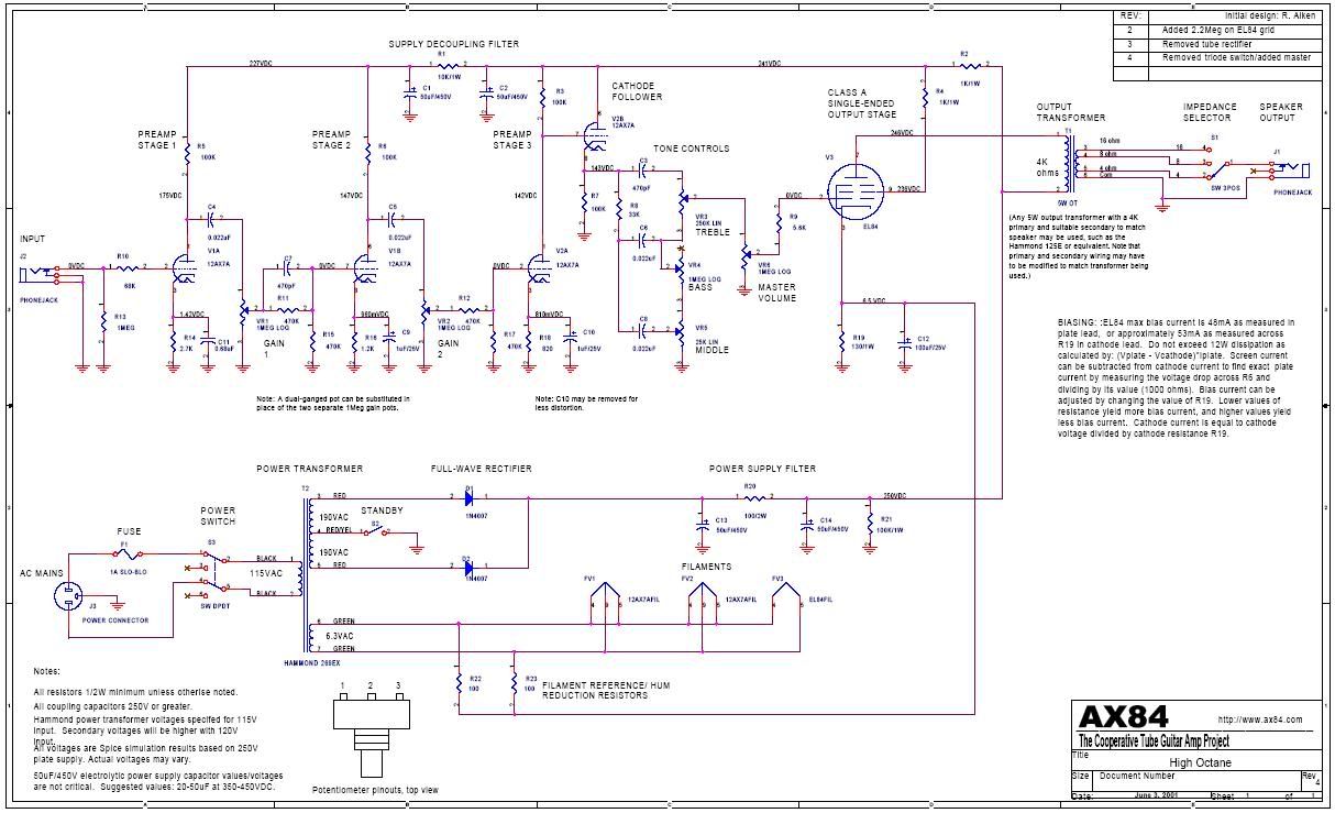
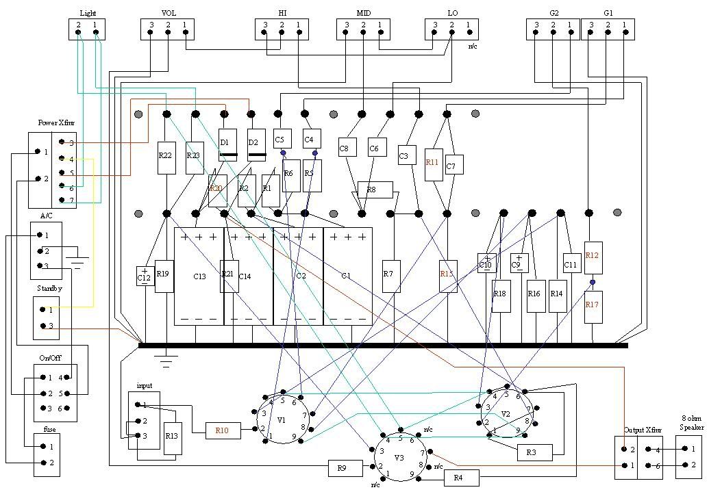
During the final stages of wiring, I realized that the output transformer (OT) designations on the High-Octane schematic are for a different transformer than what is in the attached bill-of-material.  The schematic itself does not make this clear as it mentions a Hammond 125E in a note, but does not designate what the OT on the schematic really is.  Apparantly what it refers to is the recommended OT for the P1 design (Aikens/Delft OT-5SE is designated on the P1 schematic), but the one in the High-Octane bill-of-material is an alternate OT, the Hammond 125E.  This is the OT that I am using.  The schematic shows the input at pins 1&2 and the output on pins 3-6.  The 125E has pins 1-6 markings on the output, but on the input side there are 3 pins that are unmarked.  I looked over the information at the Hammond web site and searched the ax84.com forum postings for clues about how it should really be connected.

Hammond 125E info
Hammond 125 series impedance chart

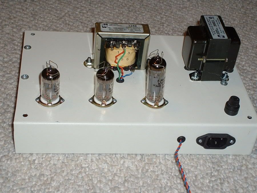
The outer two pins on the input side are to be used in place of OT 1&2 on the schematic.  The center pin is to be left 
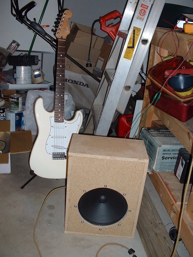
open.  I am not using an impedance selector switch since I am not making this as a head unit.  It will be connected directly to an 8 Ohm speaker; therefore, according to the impedance selection chart, I use pins 2&6 on the output side for a 4K Ohm input.  After the fact, I realized that the P1 construction guide addresses this in section 2.5.  I should have paid closer attention to this part of the document.

I finished the wiring over a week ago and after a final checkout, I plugged it in and turned it on and it worked!  I plugged in my guitar and heard the first sounds out of it.  There were two problems with it:  it had a very noticeable 60Hz buzz and when the gain is turned up high enough, it squealed very loud.  At lower gain levels, the amplified sound was sharp and clear (except for the induced buzz).  I found an old chopstick laying around the house and began poking on the wires inside to see if moving any of them had any effect on either of the problems.  I soon found a wire that was not soldered in very well.  When I corrected that, the 60Hz buzz was reduced significantly, to more of a hum, but still very noticeable; I could still hear it while playing.

I have spent some time over the last week trying to eliminate the problems.  I believe that I have the 60Hz hum corrected, but I have not yet been able to eliminate the squeal at high gain.  After reading over the P1 construction guide again, I realized that the two problems that I have are the most common with this amp design.  I pored over the forum postings on the ax84.com web site looking for clues.

My first thought was that the fields generated by the transformers could be inducing problems in each other or in the tubes, as they are all in close proximity on the small chassis that I used.  I wrapped aluminum foil around the tubes as a shield to see if that would have any effect.  It did nothing, but I had to try as it was such a simple thing to do before I got into anything more involved.  I was suspect of the filament wires thinking that they may be too close to something in the critical path.  I let the tubes warm up for a while and then I disconnected the filament wiring from the power transformer for a few seconds.  This had no effect.  I decided that the filament wiring is good.

The next thing I did was to replace the input line with shielded cable, grounding the shield at one end.  This did help reduce the 60Hz hum, but not enough.  I then moved the rectifier diodes further away from the first stage tube, V1.  I have since realized that a fundamental layout design goal is to keep the power supply section away from the preamp section.  Moving the diodes reduced the hum enough to where it is no longer a problem.  It is still present, but at such a low level that it is not worth any more effort at this time.

I have not been able to move enough wires around to eliminate the squeal, although I do believe that it is isolated to the preamp 
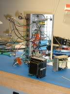
section, possibly V1.  I had to know if either transformer could be inducing the feedback (more likely the OT), so I removed them both from the chassis to the bench, and reconnected the wiring with added length to be able to displace them at least 10 or 12 inches from anything else.  I also tried to position all leads to the transformers away from any other components.  This did nothing to 
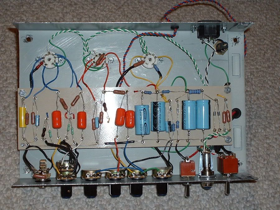
reduce the squeal or to 
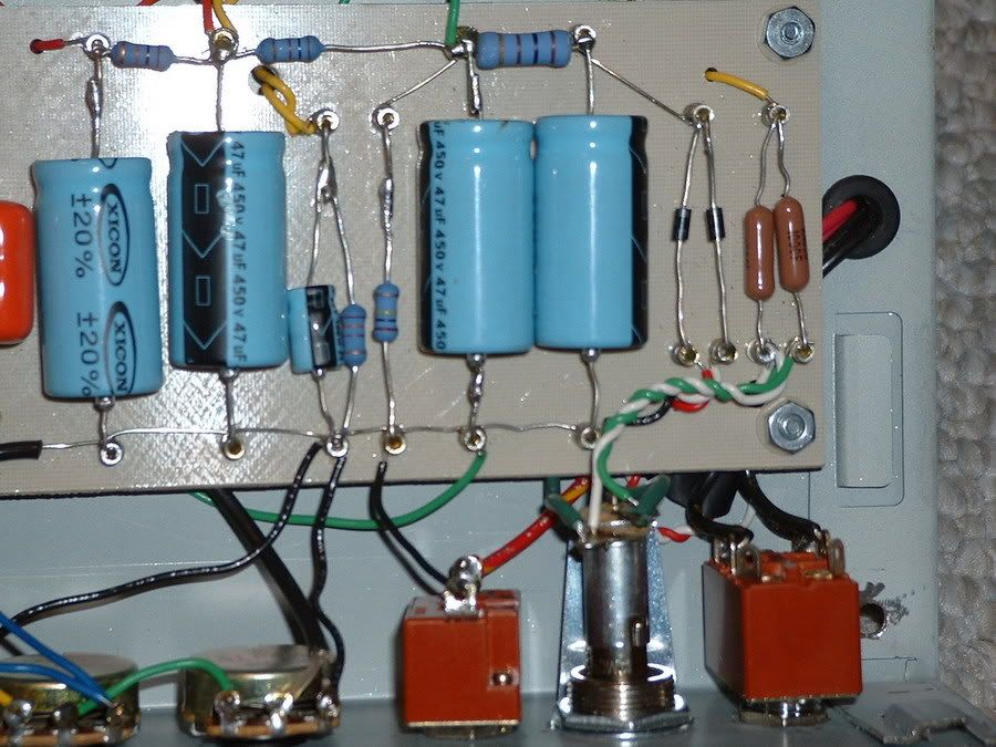
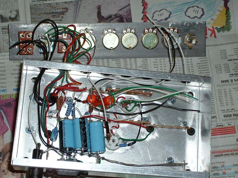
further reduce the hum.  Here's what it looks like today:


Short of a new layout, I am still trying to modify what can be reasonably done to resolve this 
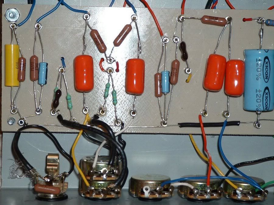
problem.  I put shielded wires on the GAIN-1 potentiometer; still no change.  Whenever I move the signal in wire at V1-2 (connected through R10) it changes the pitch of the squeal.  Moving C5 & R6 have this affect also; they are positioned very close to R10 at the V1A grid.  These components can only be moved around so much and I cannot get them into a position to completely eliminate the feedback.  My theory at this point is that the output of the PREAMP STAGE 2 is too close to the input and this is the source of the feedback.  I don't know if I can expect the preamp signal to create enough of a field to cause this feedback, but I will next try to relocate C5 & R6 to see what I get.

I did a spot check on some of the voltages at various points that were accessible to compare with the SPICE circuit simulation values noted on the schematic:


V1-1 (175V)                       V2-8 (143V)                     V3-7 (246V)


V3-9 (236V)                           C1 (227V)                         C14 (250V)


[May 31, 2004]
I finally gave up on trying to debug the amp.  I could not move the wires and other stuff around enough to make any difference towards eliminating the feedback squeal.  Plus I was in constant fear that having so many things loosened up to move around I would eventually let two exposed parts touch that shouldn't and then I'd be sinking more money into replacement parts that I had destroyed.  Also, I did get shocked a couple of times in the process and I didn't want any more of that.  Finally, the 60Hz AC hum had come back and I could not eliminate (or minimize) it 
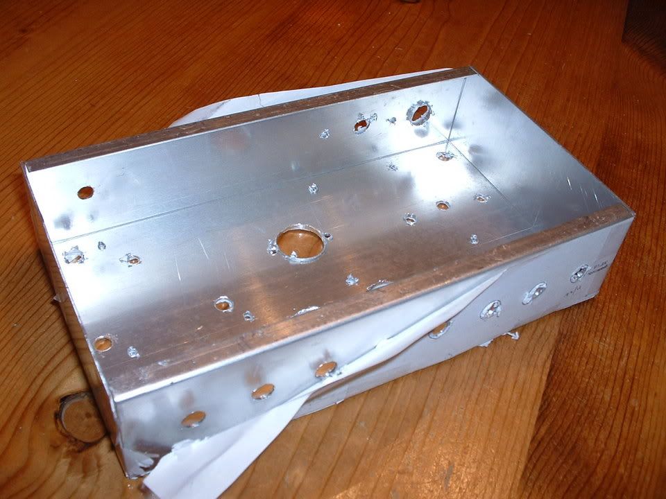
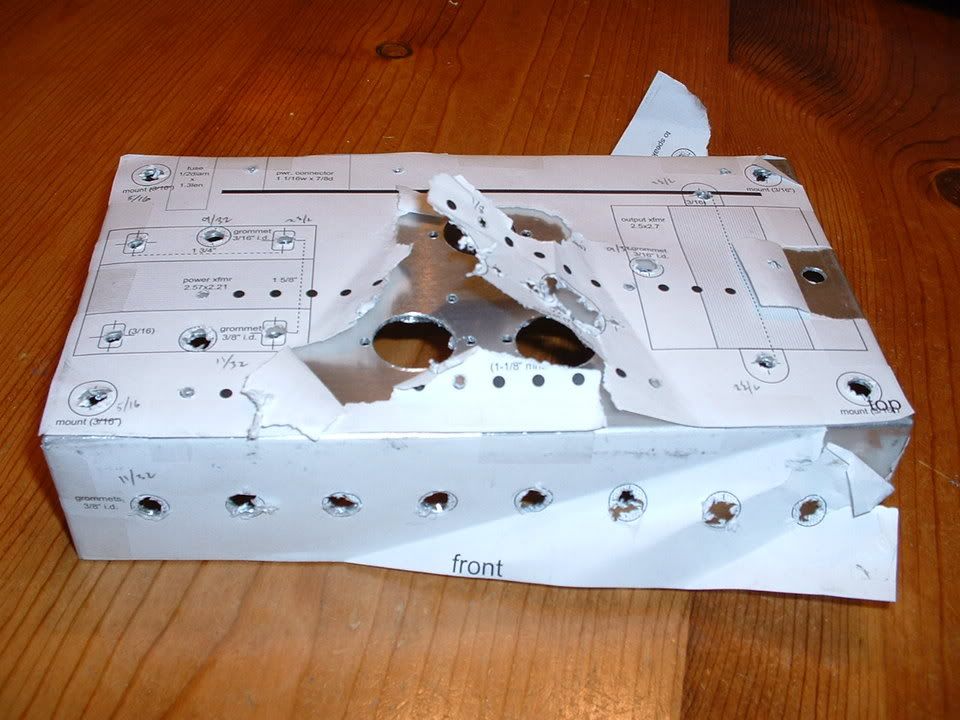
again at this point.  I decided it 
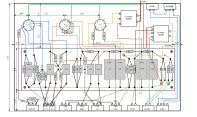
was time for plan B.....a totally new layout design.  I scrapped the chassis and wiring diagram that I had put so much time into.  
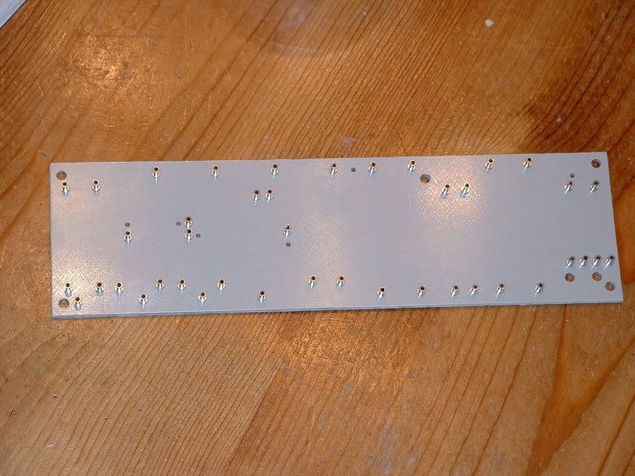
I decided that the next one would be laid out on a turret board and everything would be mounted to a properly sized chassis.

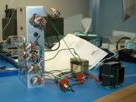
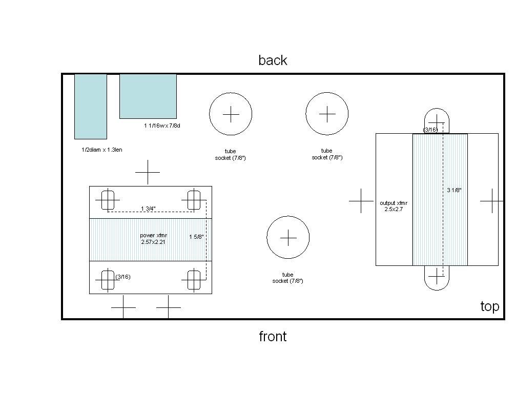
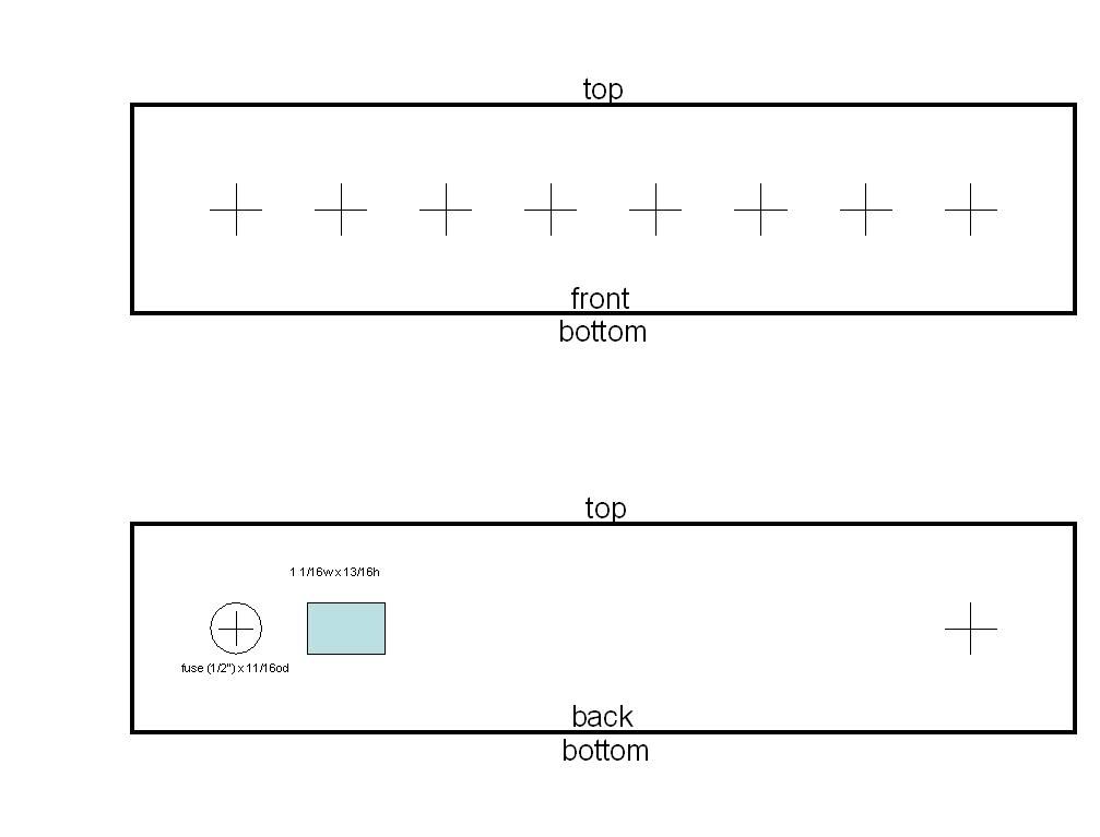
This time I decided to model my layout after one that was known to work.  I took the layout from the silvatone site listed below in the links and for the most part did a mirror-image of the layout because I still want to make mine a combo unit and mount the head in the chassis upside down.  Here's my layout:


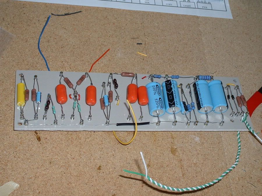
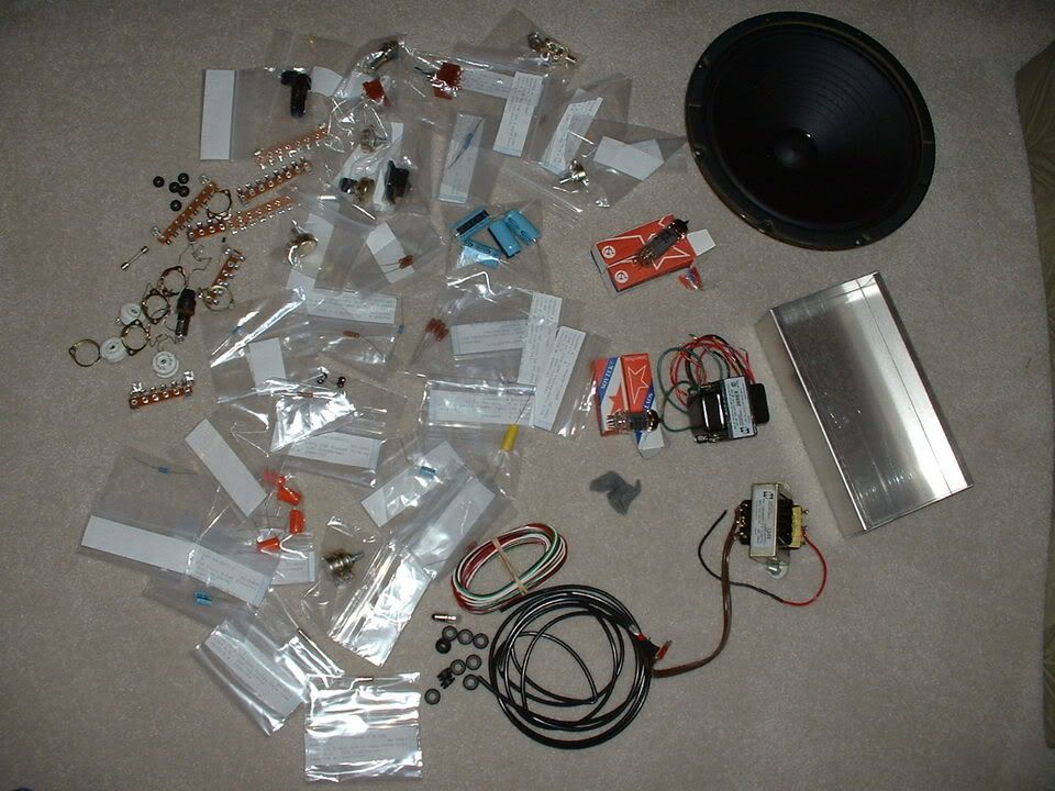
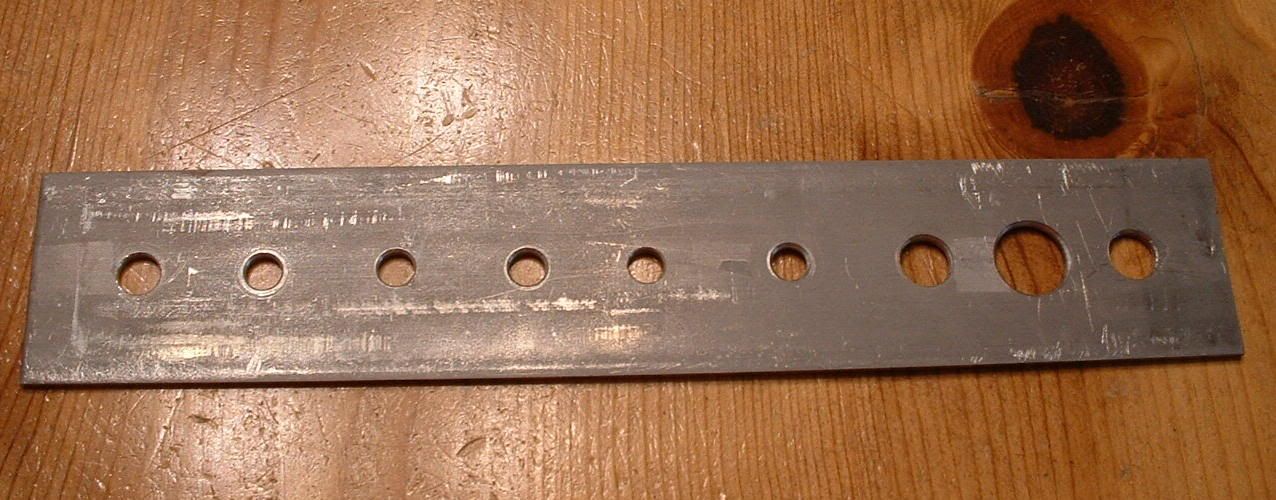
New parts had to be ordered and I cannibalized the old amp to move all components to the new one.  I bought a 12"x24"x1/8" sheet of Garolite (G-10/FR4) from McMaster-Carr to use for the turret board.  I also bought 50 turrets and a turret staking tool from Hoffman Amplifiers.  This turned out to be a real nice way to mount components.  I have enough of the Garolite left over to build 5 or 6 more amps (this should be enought for my lifetime).


I did not want to drop a bunch of money into a new blank chassis only to find out that I had yet other layout issues that had to be resolved.  I was able to get my hands on an old computer chassis....the kind that had the steel shell that fit over the top and down both sides.  This was about 7-1/2" wide and about 20" long.  I chopped it up using a jigsaw with a metal cutting blade.  I cut it so that the length was about 11-1/2" and the height was 2".


The knobs and switches are mounted in the same order and spacing as I had on version 1, but this time I moved the tubes to where there would be no components over them and I would have plenty of room to route wires around the sides and not over other wires.  I was careful to keep the filament wires away from most other wires and I used shielded wire (small coax) for the input line and for the gain signals to the pots and to the volume pot.  These wires were very difficult to work with but have been highly recommended by a number of sources that I have read on tube amp construction.  I had used a couple of them on version 1, but the really didn't make any difference when I installed them.


This layout provides for plenty of access room to all components and wires.  Here's some closeups of the wiring...


These show more detail of the chassis.  I did not drill mounting holes for the transformers at first.  I wanted to get it all wired up and then move the transformers around to be able to find a position and orientation for them that did not create feedback, induced hum, or any other interference.  It was a pain to mount them after the wiring was done because I could not remove the board and pots because the tube sockets insert in from the outside.  The front panel stuff inserts from the inside so I was able to pull them out, remove the mounting bolts from the board, and rotate it out about 45 deg so that the drill bits did not impale the components when they punched through.


I did most of the wiring and assembly last weekend.  I spent the better part of the weekend standing at my workbench in my garage putting it all together.  It must have been 90 degrees and 90 percent humidity out there.  At least it felt like it most of the time.  My feet were killing me by the time I went back to work Monday morning.

After double checking and triple checking my wiring I powered it on and it worked!  I think that it sounds pretty good.  When the gain is turned up high enough to get the dirty tone, it has no feedback as it always did with version 1.  Before I assembled version 2 I built a cabinet from 5/8" particle board to use until I can build a nice hardwood cabinet.  I will cut a hole in the top of the front so that the chassis front panel can come through when I mount it.  Before I do that, I need to double check the voltages and the power tube bias.


[June 1, 2004]
Here's an interesting read that is found on the ax84 site that describes how the P1 design works.  The High-Octane is based on the P1 design.  This document goes into a brief discussion of how tubes work also.  I found it very informative.


more to come...

Useful Links

References used for this project
          Where I bought my stuff        
AX84 Project Home

AX84 Project - High Octane

Silvatone Amp Projects - High Octane

House of Jim - Amplifier Grounding

Aiken Amplification - Safety Tips
Mouser Electronics

Ampwares

Hoffman Amplifiers

STF Electronics

McMaster-Carr


Amp Construction References
Sites That Sell Amp Parts and Kits
18 Watt Community Center

House of Jim

Tonepad

Tube Amp Webring

Harmony Central - Tube Amps and Electronics

Audionova

Small Bear Electronics

AX84 DIY Links

Amptone

Guitar Effects Oriented Webpage
       Tube Amp FAQ

Another AX84 P1 Project

Drifter Amps
       Tube Amp Safety Notes

Paul Ruby's First Startup Guide

Duncan's Amp Pages
Sherlock Amplification

JAC Music

Mojo Music Supply

Orange County Speaker

Triode Electronics

Torres Engineering

SND Tube Sales

Angela Instruments

DIY Tube

Electron Valve

London Power

Gerhart Amplification

Hoffman Amplifiers

Ultratone Amplifier

Tone Zone

STS Electronics


get this gear!