
This page is devoted to
airfoil properties
of the Dragonfly aircraft.
Click ....here.... to get back to the main page
The Dragonfly aircraft ( like its predecessor the Quickie ) was designed to use a modified version of the Glasgow University GU25(5)11-8 airfoil as its canard and the Eppler 1212 airfoil as its rear wing. There were a lot of reasons for these airfoils to be chosen, and some day, the great father in the desert may tell us what they were. For now, we can only guess.
THE CANARD :
Note : The Dragonfly " factory " issued plans do not tell the builder what airfoil was used for the canard. Best guess is that the dragonfly's canard airfoil is a variation of the Glasgow University (UK) GU25-5(11)8. Click ....here.... to read my best guess as to its pedigree. The coordinates for the original version of this airfoil are posted on the UIUC public domain website for your investigation. The file is called GU255118.dat. http://amber.aae.uiuc.edu/~m-selig/ads/coord_database.html These (original) coordinates will create an airfoil that is "close" to the one drawn on the dragonfly plans. Note : The (GU255118.dat) coordinates found on the UIUC are not going to give you the shape that you see on the Dragonfly plans. Rutan, Walters and the Q-bird boys may have started with this airfoil in mind, but over the years what ended up on the paper plans is a different airfoil.
As created by Glasgow University, the GU25-5(11)8 airfoil has a much sharper profile and higher hump than appears in the Dragonfly plans. The change may have been intentional or due to copying errors. Whatever the reasons, the "as printed shape airfoil" behaves differently than does its "pure" ancestor. You should investigate this difference. All the data in this page will be from the foil that is found on the plans, not the "pure" version.
During my study of the Dragonfly, I received a "scanned in from the printed plans" graphical file and a set of coordinate points that plotted out to make a very close version of this graphic. The data points I received can be found at drgnfly.dat . It is quite possible that reproduction errors or paper shrinkage could be the difference seen between the plotted out shape and the scanned in shape. Please see Canard Lines for a graphical explanation of the differences in the airfoil shape files and the different lines talked about in this discussion. In any event, I used the "drgnfly.dat " data coordinates for all the GU25 digital analysis shown on this website.
I relied on digital wind tunnel simulations ( computer modeling ) of the drgnfly.dat to derive my analysis of this airfoil. Today's digital wind tunnels are very good and X-Foil is about the best out there. The computer generated aerodynamic curves seen below were derived from digital analysis only. Note : computer wind tunnels tend to give results that are 0.1 to 0.3 coefficient of lift units higher than the real airfoils do. These simulated results seem to be best be compared to a real airfoil tested at Reynolds numbers near 9E6 or 12E6 (9 to 12 million). Also note that the data set does not take into account any leakage of air thru the elevator slot. The shape of the lift curve changes radically if you deflect the elevator or have gap losses.
Please see the AOA page or the Math Model page for further discussion.
GU25-5(11)8 " mod " [ drgnfly.dat ] Airfoil Profile
GU25-5(11)8 " mod " [ drgnfly.dat ] Aerodynamic Drag vs. Lift Coefficient curve
GU25-5(11)8 " mod " [ drgnfly.dat ] Lift coefficient vs. AOA curve
This is the Glasgow University GU25(5)11-8 airfoil with some chord positions marked to show important aerodynamic occurrences.
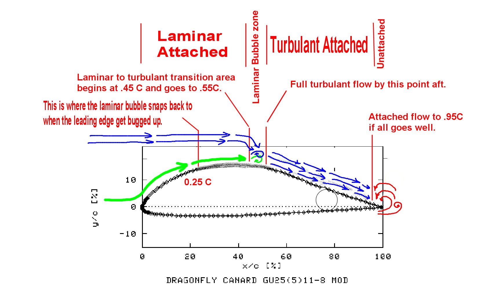
An in-depth analysis of the aerodynamic properties was conducted and presented to the AIAA in the Journal of Aircraft, Volume 25 / No. 8 on page 702 / August 1988 paper 6-2229 at the AIAA Atmospheric Flight Mechanics Conference, Williamsburg, VA August 18-20 1986. The more interesting stuff was roughed onto the graphic above.
If you are trying to crank out buckets of lift at low airspeeds speed and cant afford the weight of flaps, then this is your dream airfoil. It is laminar to 45%, attached to 95% and makes a high lift coefficient at relatively low AOA. It is by all accounts a "super-lifter". No wonder it was a human powered flight candidate.
But in the real world, you have dew, rain, bugs and imperfect fabrication. How does this affect a "super lifter" airfoil. Well, historically, the GU25 has not faired well. Painting a strip span wise will destroy its ability to raise the nose, getting it wet will cause it to pitch down in flight, getting its leading edge buggy will raise your stall speed 20 kts, building the shape wrong most likely changes the performance radically (but there has been on documentation of what the effects are). In general, these are not good things. Getting the shape right is a builder's concern, so we will not even talk about it. Water, bugs and dirt are part of the real world flying experience so we will look at these factors and how they mess with the lift of the canard.
Paint lines, water droplets and bugs all seem to do about the same thing to a GU25 airfoil. They cause the boundary layer of air just above the wing surface to trip from Laminar to Turbulent ahead of schedule. As we all know, most any airfoil has laminar flow across its upper and lower surfaces from the leading edge to about the 25% chord point. No matter how dirty or wet or buggy the leading edge gets, the flow stays attached and laminar for at least 1/4C. Now, the longer the flow stays Laminar, the lower the overall drag and the more the total lift of the surface. Clean airfoils can stay Laminar to 30 or even 40% under ideal conditions (think gliders) but if they get dirty or wet or buggy, they revert back to 25% C Laminar flow.
 The GU25 is designed to
be Laminar to at least 45% and most likely to 50% or 55%. That means that
you are only going to get the lift you are expecting from it if it stays Laminar
to its max aft chord station. If bugs mess up the transition point, that
means that the laminar to turbulent flow reverts to the 25% chord
position. That means 20% to 30% more of the chord is now experiencing turbulent
flow than is expected. Now Turbulent flow is still attached flow (so
you are still making lift) but it is not as good a lift making flow as
Laminar. Lets say Turbulent flow is 50% less effective at making lift than
Laminar flow.
The GU25 is designed to
be Laminar to at least 45% and most likely to 50% or 55%. That means that
you are only going to get the lift you are expecting from it if it stays Laminar
to its max aft chord station. If bugs mess up the transition point, that
means that the laminar to turbulent flow reverts to the 25% chord
position. That means 20% to 30% more of the chord is now experiencing turbulent
flow than is expected. Now Turbulent flow is still attached flow (so
you are still making lift) but it is not as good a lift making flow as
Laminar. Lets say Turbulent flow is 50% less effective at making lift than
Laminar flow.
That means that as compared to a clean, dry, happy flying canard, at least 20% of the chord ( and that works out to be 20% of the total canard area ) is now making 50% less lift. The math looks like :
Lift Loss = 0.20 * 0.50 = 0.10. ( 10% ) So now that the leading edge has a few bugs on it the entire canard is now making 10% less lift. If you are counting on that lift to keep your nose up, you are in for a rude surprise.
Not all wings are created equal. some airfoils are sensitive to boundary layer tripping (like the GU25) and some are completely insensitive to it (like the NASA LS(1)-0417 mod family). The trick is to have an airfoil that cranks out the lift and is not sensitive to bugs and rain. This airfoil would be able to do the work of the canard and still be counted upon in bad weather or at the end of a long flight to a sub-tropical sky (full of bugs).
 Enter the Roncz R1145MS "Rain
Canard".
Enter the Roncz R1145MS "Rain
Canard".
This was the factory recommended replacement airfoil that J. Roncz developed for the LongEz. It was accepted by most every design using canards except the Dragonfly and Q-desins.
This airfoil is pattered after the NASA LS(1)-0417 mod airfoil, and if installed correctly will deliver better performance over a wider range of surface conditions. In theory, the R1145MS is more efficient at making lift than the GU25 so you get to use less of it. The elevator constitutes a larger percent of the canard chord (38% vs 25%) so it constitutes more of the lift of the canard system, thereby making the stick control less sensitive. The airfoil is slotted, so its turbulent flow boundary layer stays attached longer and over a wider range of "en-bug-e-fied". This is good. The elevator is "slotted" not "plane" so the elevator can be deployed farther to make more lift. This is good but an un-utilized benefit of the design. It takes less slotted elevator deflection to make the same lift as a plane elevator so deflections can be reduced. Less deployment means less aerodynamic stresses on the system. The R1145MS is derived from the family of high speed airfoils that NASA developed for general aviation. Starting with the 63 and 65 series progressing to the GAW-1,2 and finally to the LS(1)-04XX series these were airfoil created for Reynolds Number operations in the 2 to 12 million range with low moment and deep drag buckets. It appears that J. Roncz fixed the pressure recovery cusp issue and tweaked the LS wing to make his R1145MS. The R1145MS is thick and blunt nosed. Two things you want for a canard. It is fairly benign to being made wrong (shape wise).
THE AFT WING :
Aft Wing Note : The Dragonfly "factory" plans call do not tell the builder what airfoil is used for the aft wing. My best guess is that the airfoil section is a variation of the EPPLER 1212 airfoil developed by Dr. Eppler. The coordinates for the original version of this airfoil are posted on the UIUC (public domain) website (see above) for your investigation. The file name is e1212.dat There is another file just below this one titled "e1212 mod" that is labeled for the quickie aircraft. This "mod" version is very similar to the "e1212" except for a shift in the chord line that causes a strange built in incidence. We did not use this file and do not recommend using this shape file for anything. We used the e1212.dat data file and clearly understand that the "chord line" is the only line that means anything when it comes to correctly installing a wing onto a fuselage.
The original data coordinates set e1212.dat will create an airfoil shape that looks a lot like the one on the D-Fly plans. An ACAD 14 drafting file of these data points may be seen by clicking Eppler 1212 shape . We also have a set of ACAD 14 format, digitized, aft wing coordinates ( courtesy of One Sky Dog ) These coordinates were overlaid onto the e1212.dat set for comparison. With the exception of some paper shrinkage errors and aileron alignment mistakes, there is no difference in the shape files. There is a 0.5288 degree difference between the true chord line of the Eppler 1212 airfoil and the "install line" as shown on the digital scan of the D-fly aft wing. That is to say, if you install the plans built wing with the install line at "level" you are actually installing the airfoil with a 0.5288 degree AOA to the relative wind.
A graphical comparison of these data files can be seen by clicking comparisons . Owen Strawn (DF builder and designer) picked up on this problem some time ago and has done his very best to get the D-fly community to pay some attention to this very serious consideration. His information may be found at http://home.earthlink.net/~owenstrawn/images and has contributed greatly to the information on this concern.
In any event, all computer math models (simulations) assume that the only line you care about is the "chord line". The imaginary things called "install lines" or "level lines" or "water lines" will never be mentioned, considered or even acknowledged in an aerodynamic analysis. For our digital wind tunnel simulations ( computer modeling ) we used the original Eppler 1212 data set to create the output curves seen below. Note : computer wind tunnels tend to give results that are 0.1 to 0.2 units higher (near stall) than the real airfoils do. These are ideal curves that would best be compared to a real airfoil tested at Reynolds numbers near 9E6 or 12E6 (9 to 12 million). Also, the aileron is not deployed at all in these simulations. Deployment of the aileron will radically change the shape of the curves.
Eppler 1212 Drag vs. Lift Coefficient curve
Eppler 1212 Lift Coefficient vs. AOA curve
revised 10/21/2002

![GU25-5(11)8 " mod " [ drgnfly.dat ] Airfoil Profile](https://www.angelfire.com/on/dragonflyaircraft/images/CANARD.gif)
![GU25-5(11)8 " mod " [ drgnfly.dat ] Aerodynamic Drag vs. Lift Coefficient curve](https://www.angelfire.com/on/dragonflyaircraft/images/CANARDcd.gif)
![GU25-5(11)8 " mod " [ drgnfly.dat ] Lift coefficient vs. AOA curve](https://www.angelfire.com/on/dragonflyaircraft/images/CANARDcl.gif)