This
page is dedicated to
the topic of Angle of Attack ( AOA )
and its importance on the act
of staying in the air.
click < here > to go back to the main page
First : some
definitions.
AOA
: Is the angle of attack that the airfoil is experiencing.
Classically defined as the angle between the free stream and the chord line
of the airfoil. This angle may change due to elevator (aileron) deployment even if
the angle of the attached aircraft does not change.
Chord
line :
An imaginary line drawn from the point of forward most curve of the
leading edge to the very tip of the trailing edge. Used to separate the
"upper" surface from the "lower" surface when giving the initial
coordinates of the airfoil. this is the line that (for the most part) is used to determine the AOA of the
airfoil. Note: if the trailing edge were to be displaced downward, the chord line
would change to follow it. We generally call this sort of thing a control
surface and have them on our airplanes (ailerons, elevators, etc.) .
Cl
: Coefficient of lift.
This is a non labeled ratio that defines the lifting capability of an airfoil with
respect to other airfoils. The higher, the better for making lift. 1.8 is
about as high as an un-assisted airfoil is going to get. With the addition of flaps,
leading edge slats, or recurring, the value can get as high as 3.8.
Alpha
: The Greek symbol for small "a" is the angle of attack of the airfoil as seen
in the lift curves (this is AOA). Typically between -5 and 25 degrees.
Gamma
: The
Greek symbol for small "g" if for the angle of deployment of elevator (or aileron) segments of airfoils as
seen in the lift curves. Typically no greater than 40 degrees.
AOA and its affect tandem wing flight :
You can not believe how confusing this topic is and how
much debate on flying : for now, i am going to put in a disertation from
Dave Gall that i dont fully understand, but i think is correct.
(New guy
makes first appearance on list, stirs up trouble in sunny FL...)
You are
correct that the moments made by the airfoils are not getting enough attention
in the tandem wing discussion. I would surmise that X-Plane is giving you a
qualitatively correct picture of the situation.
The
contribution of the fuselage is not likely to be significantly changed between
the two fuselage attitude angles that you reported, nor are the moments
generated by the changed heights of the drag forces significantly different
between the two cases. Ignoring these factors (and any thrust effects) and
investigating just the wing and canard, it should be easy to spot the
contribution of the moments at the two different flight conditions. In fact,
just general knowledge of normal cambered airfoils is sufficient to show
that there should be a different fore-aft lift distribution just like the
one you report from X-Plane:
Fact: most
cambered airfoils have a negative pitching moment. Assume that it is a
constant at all angles of attack (a not unreasonable assumption). In your
first flight condition, you were showing 120 mph, and in your second you
showed 180 mph. By simple ratios, it is apparent that the pitching moment of
each lifting surface (wing and canard) is 225% greater at the higher
speed, since pitching moment is proportional to the
coefficient-of-pitching-moment (Cm) multiplied by the square of the speed. You
increased the speed by 1.5, so you increased the pitching moment of each wing
by (1.5)^2=2.25. This increased total-airplane pitching moment must be
balanced by a change in distribution of lift between the two wings. But
wait....
The effect
is partially cancelled by the reduced pitching moment coefficient expected
from the "reflexed" trailing edge and the reduced elevator
deflection, but by how much? Certainly, those who argue that the lift
distribution is ALWAYS EXACTLY the same because "the lift
force" has to balance at the same location as the un-moved CG have
confused the apples with the oranges (sorry, Ted). Their argument would have
to consist of asserting that the reduced Cm of the reflexed trailing
edges must necessarily always exactly cancel the increased pitching moment due
to higher speed. That's a dubious connection at best, but also easily
disproved: Every positively-pitch-stable airplane that flies requires an
elevator displacement to fly at a lower or higher speed, thus discrediting the
asserted always-constant lift distribution between the front and rear wings.
Would these same people argue that the changed pitching moment of the TAIL
exactly balances that of the wing at higher and lower speeds? Then what of all
that we learned of tail-down-force in private pilot school? Are these people
now asserting that the tail does its job by trying to TWIST the fuselage (in
pitch) about the horizontal stabilizer spar? I think not.
But what's
happening with the Raptor? At the higher speed, you show the rear wing being
required to make MORE lift than had been required of it before. Apparently,
the total airplane pitching moment is LESS at the higher speed, indicating
that the effect on pitching moment of the reflex and reduced elevator
deflection is MORE POWERFUL than the effect of the speed. Does this make
sense? Yes. Whereas the speed would have increased the pitching moment by a
factor of more than two, the retraction of a flap has the ability to reduce
the pithing moment COEFFICIENT by a factor of five, ten, or more, or even to
make it change sign (become positive). If you multiply a negative number by
2.25 then divide it by five, or ten, or even a negative number, the result is MORE
POSITIVE than what you started with, so it makes sense that the total
airplane pitching moment would be more positive at higher speed, thus loading
the rear wing more and unloading the canard.
Does this
relate to what is observed in conventional airplanes? Somewhat: retract the
flaps on any spam-can and see if you don't also have to relax back-pressure to
maintain altitude. You'll also notice an increase in airspeed. I think that's
ample evidence of a positive-changed Cm. However, try flying that spam-can the
way the Raptor is flown: dial in an elevator setting and clamp it in
place (reflexor), then try to find the flap setting that keeps you out of the
ocean. Dial in more trailing-edge-up on the elevator (reflexor) and you
will quickly find yourself flying with the flaps in a different setting, but
perhaps NOT more retracted as would be correct in analogy with tandem wing
planes. This is because the flaps (elevators) on tandems are ahead of the CG
whereas the flaps on conventional planes are aft of the CG.
That
discrepancy notwithstanding, since Private Pilot school we have fooled
ourselves into thinking that more up-elevator has meant more down force on the
tail, but as we have just shown the opposite is actually the case. More up
elevator means more down force INITIALLY, but once equilibrium is attained
(either by flying slower or changing flap settings) the actual FORCE created
by the horizontal stab/elevator on conventional planes is MORE POSITIVE ("less
downforce") due to the changed airplane pitching moment. On tandems, the
rear wing starts out lifting, so more positive means that it has to lift more.
This condition is initiated by "more up elevator" on conventional
planes, which translates to "trailing-edge-up reflexor" on tandems.
Finally, equilibrium is attained on tandems by a changed "flap"
setting (more trailing-edge-up on the canard). This gives the happy benefit of
a FASTER speed due to reduced canard lift and drag.
To recap:
Trailing-edge-up reflexor allows for faster flight by "unloading"
the canard. This also puts more of the lift load on the rear wing, which
suffers the disadvantage of having "retracted" its "flaps"
to cause this condition. The rear wing thus flies at a higher angle of attack
and has a lower critical (stall) angle of attack, so it flies with less margin
below its stall angle. The canard flies with less load and has its
"flap" (the elevator) more retracted, while flying at a slightly
increased angle of attack, but not as much so as the rear wing (I won't bore
you with downwash explanations). Thus, the canard has a larger margin below
its stall angle of attack than it did previously, and is capable of larger
multiples of its current lift load. That last translates into an increased
load factor capability, or in other words, the up-reflexor gives the airplane
a potentially LOWER maneuvering speed and stall speed. However, the rear wing
is working harder and may be potentially able to stall BEFORE the canard
stalls (is that your "wicked evil stall?").
I think it
would be prudent to set VERY conservative limits on the allowable deflections
of any reflexor, recognizing that at any given CG location, down reflexor can
increase canard stall speed (relatively benign) and up reflexor may cause main
wing stall (not nice). With that in mind, a careful envelope expansion would
be needed to determine the useful/allowable reflexor positions for various CG
locations, and the cruise/stall speed performance benefits of same.
It is
particularly instructive (and of great credit to Austin Meyer and his X-Plane
program) to note that the giant analog computer in the sky is giving you the
same answers as the PC: take heed!
Opinions
expressed are my own,
David J.
Gall, BSAE
Gamma and its
affects on AOA :
In tandem wing
designs, the maximum angle of attack (AOA) that the forward wing (canard) can achieve is
greatly influenced by the deployment of its trailing edge. In most of the classical
analysis literature, if you move anything on the trailing edge, it is called a flap.
When you are talking about "canard" or "tandem wing" aircraft,
the trailing edge of the front wing is called the elevator. Deployment of the
"elevator" is typically given the Greek symbol of gamma.
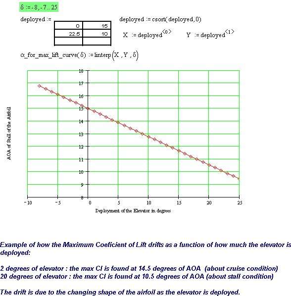
The lift curve
of the GU25-5(11)8 mod airfoil is greatly affected by the deployment of the elevator.
For example, when the elevator is in the neutral trailing position (just
hanging straight back) the max AOA of the airfoil occurs at a quite normal angle of 16 or
17 degrees. When the GU25-5(11)8 mod airfoil's elevator is deployed, however, the
situation changes radically. At an elevator deployment angle of 20 degrees (gamma),
the airfoil's max AOA is achieved at a very low 10 or 11 degrees. Any attempts
to pull the nose up more only creates stall and pitches the nose down. This tendency
severely limits the AOA of the fuselage (and the aft wing that is attached to it).
Click < here > to se a graphic of the effects of "gamma" vs
"Stall AOA" for the GU25-5(11)8 mod airfoil. As the angle of deployment of
the elevator (gamma) goes from 0 to 20, the stall AOA goes from 16 to 11 degrees.
AOA and its
affects on shed vortex :
The inevitable
result of generating lift is to generate turbulence. At high AOA's, the forward wing
of a tandem design generates a lot of turbulence in the form of shed vortex wake.
This screwed up air trails backwards and will wash out any lifting surface behind
it if it can. The trick, if you can do it, is to not let the aft lifting surfaces
fall into the shed vortex wake.
As a tandem wing
aircraft rotates about its center of lift, the aft wing tends to translate (vertical
movement downwards) into the shed vortex wake sheet of the forward wing. If
your forward wing is huge, like ours is, this is a very bad thing. Large, hard
working wings generate a huge amount of disturbed air behind them. The fact that
your aft wing is bolted to the fuselage only makes it worse. You, the pilot, are
expecting the aft wing to keep on lifting its fair share of the load no matter what air it
has to pass through. When the aft wing translates into the shed vortex sheet, its
ability to create lift is greatly reduced. Lots of other bad stuff happens also, but
the net result of pulling the nose up and screwing up the air for the aft wing is a very
serious loss of aft wing lift. In its worst case, this loss of aft wing lift
is called "deep stall". This is the condition were the forward wing is
still lifting and the aft wing has completely stalled. This very depressing case
allows the tail of the aircraft to sink down even more....pulling the aft wing even deeper
into stall. From this condition, there are few recovery options.
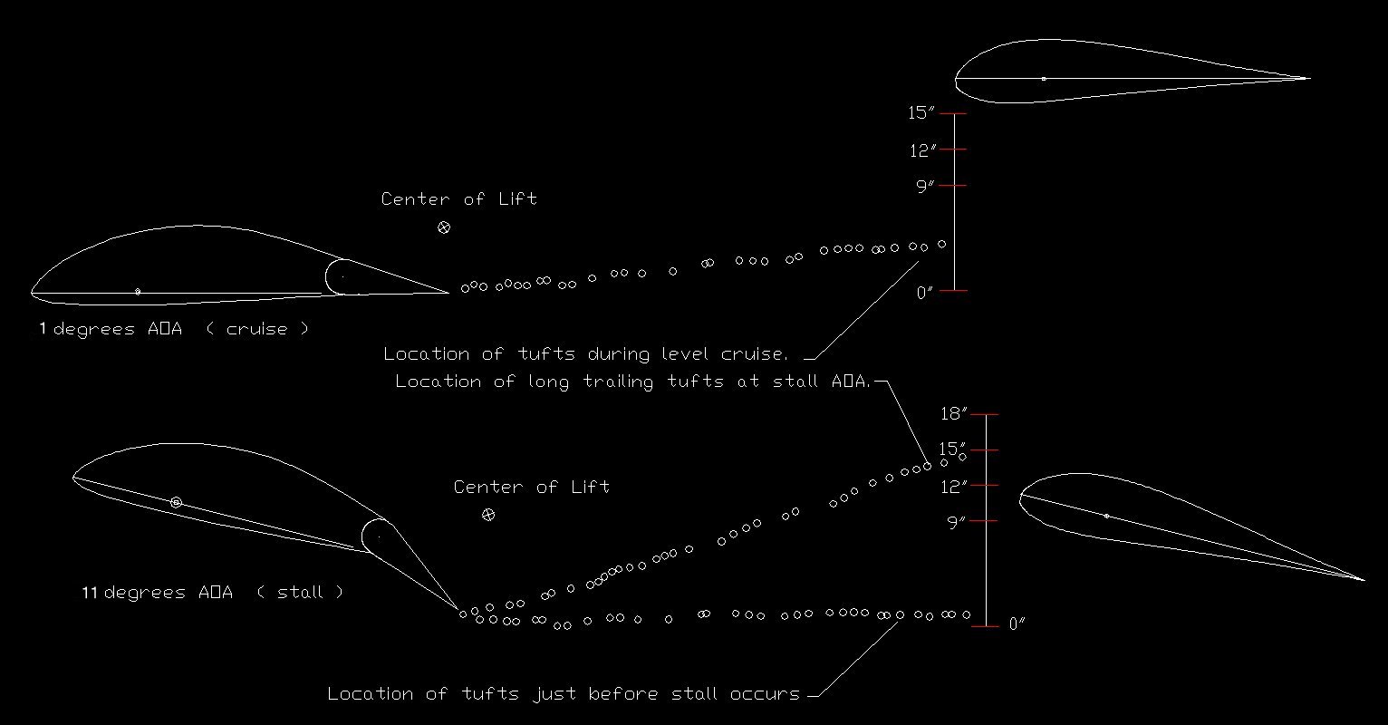
Click < here > for a
graphic
interpretation of some "basic" data on the flight behavior of a
typical Mark II D-Fly. Note : This is an interpretation of data given to us from a
builder / pilot. The graphics show a GU25-5(11)8 canard with a 20% elevator as it
was observed in flight. This is only a rough image of what is going on out there in
the wind, so do not read more into the graphic than it shows. As the angle of attack
of the forward wing is pulled to stall AOA, the shed vortex sheet over takes the aft wing.

