
Here is a method of using the same digital I/O pin of a PIC microcontroller for both input and output purposes. It can be used on regular I/O pins but not those having a Schmidt trigger input circuit. Here is the schematic diagram.
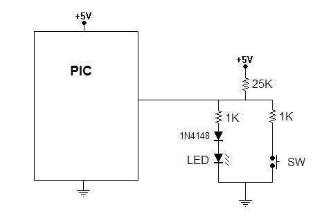
To use this method, the PIC should be programmed to keep the I/O pin set to be an output most of the time. When it is an output, it will be driving the I/O pin either to 0 volts (causing the LED to be off) or to +5 volts (causing the LED to be on). Pressing the push button switch would cause the PIC to have to supply more current when the I/O pin is outputting +5 volts, but otherwise, the effect would be negligible.
Periodically, the PIC program should change the I/O pin to be an input pin for a short time. During this time, the I/O pin assumes a high impedance. That means it does not drive the pin high or low. The voltage on the pin is allowed to float according to what is coming in from the external world. Therefore, we have two cases to consider.
In the first case, the push button is being pressed so the input pin sees a simple voltage divider that results in less than 0.2 volts at the I/O pin. The LED, the 1N4148 diode, and their associated resistor do not play into this because 0.2 volts is too low to overcome the forward voltage of the diodes and they do not conduct. With 0.2 volts into the I/O pin, the PIC program will read the state of the input as a logic zero.
In the second case, the push button is not being pressed so the voltage on the input pin rises due to the 25K pull up resistor. However, it will not rise to +5 volts because the diodes will begin to conduct. The 1N4148 diode has a forward voltage of 0.6 volts. Combined with the forward voltage of the LED, the total will be at least 2.3 volts. The 1K resistor associated with the diodes will add another 0.1 volts so the voltage on the I/O pin will be at least 2.4 volts. This will reliably be read by the PIC program as a logic one. Notice that the LED will be lit in this case, but only dimly because the 25K resistor and the 1K resistor associated with the diodes limit the current to only about 0.1 milliamps.
Even that does not matter much because the PIC program should be written to only keep the I/O pin moded as an input pin for a short time whenever the button is to be sampled. The dim glow of the LED will never be seen due to the fact that it is only present for perhaps 15 microseconds during this sampling.
Here are a few more considerations in using this technique. First, diodes actually have a bit of capacitance. I have found that if I switch from output mode to input mode and then immediately sample the input state of the I/O line, I may get a false reading due to that capacitance. The solution is simply to wait for perhaps 10 microseconds after switching the pin to input mode before reading the I/O pin.
Another tip is that many I/O pins of PIC microcontrollers have optional internal weak pull up resistors. If the internal pull ups are enabled, the 25K resistor may be omitted.
Another tip is that blue and white LEDs have higher forward voltage drops than do many of the other colors. If you use a blue or white LED, you can avoid the need for the 1N4148 diode.
Of course, there is nothing in this circuit that replaces the need for the PIC program to perform proper debouncing of the switch signal so you still need to deal with that in the PIC program design.
Since the use of the LED as an indicator is not affected by pressing the button, other kinds of switches can be used instead of a simple momentary push button switch. For example, a toggle switch could be used.
I hope you enjoyed this slick PIC trick.
Send comments to:
![]()
