
Here I am presenting a challenge for somebody else. I would like to see it done. This would be a good project for somebody who likes to work on bootloaders, particularly serial communications bootloaders. Building on the ideas embodied in the DBg In-Circuit Debugger, this would yield a new combination of features with very minimal hardware expense.
If a system is going to employ an in-circuit debugger based on the built-in PIC debugging circuitry, then RB6 and RB7 MUST be set aside for that activity. The hardware forces that.
My DBg project shows that a debugger can be implemented using little more than a USB-to-TTL serial converter for an interface and an ordinary terminal emulator program running in a PC. It occurred to me that it would surely be slick if the bootloader could operate through that same USB-to-TTL serial converter and not need the USB interface facilities of the PIC18 series chip.
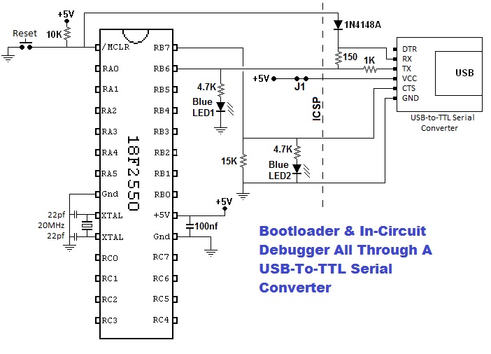
I included the blue LEDs in the schematic simply to show that the RB6 and RB7 pins could still serve a purpose for the finished user application when the bootloader and debugger are not running. White LEDs could be substituted. The LEDs along with their associated resistors can be considered optional. Blue and white LEDs have higher forward voltage drops than LEDs of most other colors. Their high brightness permits the use of a fairly high resistance current-limit resistor. This means their loading effects are minimal.
This is included so that a PIC system that has its own power source could operate with the USB-to-TTL serial converter interface without that converter providing the +5V power for the PIC system. If no other power source is available, leave the J1 jumper connected. If there is an alternate source of power, open the J1 jumper.
When characters are to be sent from the PIC system to the PC, RB6 is moded to be an output and the serial bit stream is sent via RB6. As in DBg, the serial line idles at a 1 between characters and pulses to 0 briefly in the correct pattern to send each character. The serial data thus generated passes from RB6 out through the 150 ohm resistor to the RX pin of the USB-to-TTL serial converter so it can be transmitted to the PC and displayed by the terminal emulator. At the time RB6 is sending these characters, there is negligible influence from the TX signal from the USB-to-TTL serial converter due to the intervening 1K resistor because RB6 is being driven high and low with a very low impedance.
When characters are to be sent from the PC to the PIC system, RB6 is moded to be an input and the serial bit stream is received via RB6. Again, just as in DBg, the serial line idles at a 1 between characters and pulses to 0 briefly in the correct pattern to send each character. The serial data passes from the TX pin of the USB-to-TTL serial converter through the 1K resistor and into RB6. Since RB6 is very high impedance when it is moded as an input, the intervening 1K resistor has only negligible effect on the data that passes through it. A side effect is that any serial data received in this way also travels out through the 150 ohm resistor to the RX pin of the USB-to-TTL serial converter and back to the PC where it will be displayed by the terminal emulator.
If you have familiar with the internals of DBg, you will see that characters received by DBg are echoed back to the PC so the operator can see what he/she is typing. Therefore, this built-in auto-echoing of received characters does not present a problem.
Since we are proposing that a bootloader be included in this project and still wanting to stick with just a simple terminal emulator for the PC software, the HEX file to be loaded via the bootloader will be sent over the serial line to the PIC system and, due to this auto-echo of all received characters, the operator will just have to put up with seeing a copy of the HEX file being displayed on his screen. That does not seem like much of a problem to me.
One might wonder why we should bother to squeeze all the serial I/O through a single pin, namely RB6. The reason is that this frees up RB7 for use as a flow control pin during bootloading.
When the PIC system bootloader program is receiving characters of a HEX file, it must store the received data into Flash memory (and sometimes into EEPROM or the Config registers). The action of writing to these memory devices is much slower than when a program writes to RAM. Each write cycle takes something like 2 milliseconds during which time the PIC essentially becomes inert. Even at moderate serial communications speeds, that much delay would prevent proper reception of serial data. The only solution is to cause the PC to stop sending for a short time while the writing action takes place and then let the process resume. We could use an XON/XOFF protocol for that but probably a simpler approach is to use the RB7 pin to signal when it is OK for the serial data to flow from the PC to the PIC system and when it is not.
The schematic shows the RB7 signal connected directly to the CTS (Clear To Send) pin of the USB-to-TTL serial converter. During the bootloading operation, RB7 should be moded as an output and held low until the time that writing is to be done. This low signal to the CTS pin tells the PC that it is OK to send its data.
When the bootloader needs the stream of serial data to stop so that it can perform a write-to-memory operation, it should set RB7 to a high condition which, via CTS, will cause the PC to stop sending characters. However, this stopping action is not instantaneous. There may be two or three characters already in transit that cannot be prevented from making the trip. Therefore, when the bootloader sets RB7 to a high to stop the PC, it needs to continue to operate in the receive mode for a bit longer until serial characters are no longer arriving. This could be done for a fixed time period or it could be done by waiting until the serial line (on RB6) remains high steadily for some given period of time. Either way, any characters that do manage to arrive must be buffered so that when the write operation has subsequently been carried out and the bootloader is again able to receive, it must begin by processing any characters that were buffered. Then it can set RB7 to a low so that the PC will resume sending.
At times when the PIC bootloader/debugger software is operating in debugger mode, RB7 should be held low to permit characters typed by the operator on the terminal emulator in the PC to be sent to the PIC system.
The undocumented debugging hardware in the PIC chip makes it necessary to use RB6 and RB7, especially RB6. There is a special feature related to RB6 and the PIC chip's hardware debugging mode. When operating in debug mode, if the user program is running and the operator wishes to interrupt it and regain control via the debugger software, a high-to-low transition is required on RB6 to cause that. When interfaced via the USB-to-TTL serial converter, simply typing any key into the terminal emulator sends such a high-to-low transition on RB6. The presence of the 15K resistor from RB7 to ground assures it is held low should RB7 be moded as an input during such times.
When the Reset button is pressed (just as in DBg), the diode assures that RB6 is low which prevents erroneous startup conditions (for reasons not totally clear). The 150 ohm resistor is present only to limit any very short term in-rush current that might result if Reset is pressed while RB6 is moded as an output and outputting a high.
When Reset is pressed, control will be directed either to the Reset Vector at 0x00000 or to the Debug Vector at 0x200028, depending on the state of the DEBUG bit in the configuration registers and the other conditions that affect entry into Debug mode. Either way, the system can be set up so that control will arrive in the bootloader/debugger software package. Serial communications could be conducted via RB6 and RB7 in either case.
Suppose Debug mode is disabled via the configuration registers. How should the bootloader/debugger know whether to start the application software that is already loaded or to start the bootloader? There are several options available here.
Option 1 - Bootloader Button It is possible to connect a normally open Bootloader pushbutton from RB7 up through a 270 ohm resistor to +5 volts. Upon reset, the software could mode RB7 as an input and read its state. If 0, the Bootloader button is not pushed and the user application could be started. If 1, the bootloader could wait for the release of the pushbutton (indicated by it returning to 0) and then await a HEX file to arrive via RB6 while using RB7 for flowcontrol.
Option 2 - Timeout It is possible to have the bootloader/debugger software mode RB6 and RB7 appropriately for serial communication. If no HEX file begins within a set period (perhaps 3 seconds), the user application is started. If the HEX file does begin, the bootloader loads it.
Option 3 - Test RB6 If a large resistor (perhaps 15 K) is connected from RB6 to ground, when the bootloader/debugger software begins, it could mode RB6 for input and test the state of that signal. If it is 0, the USB-to-TTL serial converter electronics is not present and nothing is connected to the ICSP pins. In that case, the user application that is already loaded should be started. On the other hand, if the RB6 pin is 1, the USB-to-TTL serial converter is present and holding the RB6 pin high. Serial communications can be initiated with the PC. If the operator wants the user application to start, he/she can type some suitable command (perhaps "G" for GO) to start it. Sending a HEX file could trigger the user of the bootloader.
Well, there it is. I have planted the seed. Maybe somebody will also think this is a cool idea and help it come to life. If I were more of an expert on how bootloaders really work, I might be tempted to do this myself. But for the moment, I have other projects begging for my time. I just did not think it best to totally ignore this obvious idea that was dancing in my head.
HOME
To email me, send to:
![]()
