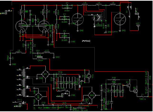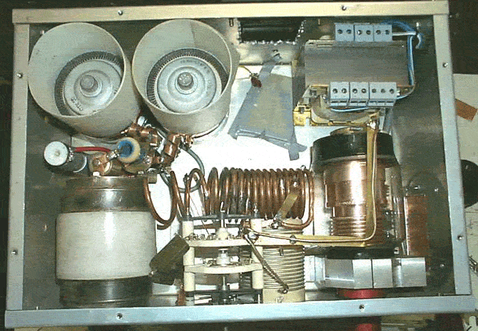
PLEASE LET IT LOAD TO VIEW ALL THE PICS.
4CX2500A/GU-84B
SVETLANA POWER TRANSMITTING TETRODE
The GU-84B is a ceramic-metal forced-air cooled tetrode intended for use in power amplifiers with distributed amplification and for SSB-signal amplification with output power up to 2.5 kW at frequencies up to 75 MHz as well as for power amplification at frequencies up to 250 MHz with output power up to 2.2 kW in radiotechnical equipment.
The Svetlana 4CX2500/GU-84B is manufactured in the Svetlana factory in St. Petersburg, Russia.
GU-84b is the military version of the Svetlana tetrodes.Typical use would be transmitters "PLAMYA" ("FLAME"-eng.),used on submarines.In emergency mode GU-84B can work without cooling aproximately 20-30 minutes.Many amateur radio stations see 4 KW in SSB and CW modes. They use GU-84B in long-lasting contests.
CHARACTERISTICS:
Intermodulation distortion of the 3rd order - minus 35 dB
Anode Dissipation - 2.5 kW
Screen Dissipation - 30 W
Grid Dissipation - 1 W
Frequency for Max. Ratings- 250 MHz
Cathode... Oxide coated Heater voltage - 27 V
Heater current - 3.7A
Transconductance at Ua= 1.5 kV Ug2 = 375 V Ia = 2 A -->75 mA/V
Capacitance Input /Output /Feed-through / -115 pF /23 pF/0.2 pF --> Max
Seal and Envelope Temperature -200° C
Maximum Length -115 mm Maximum Diameter -99 mm
Weight-1.4 k g
Operating Position -Any
Blower -120 m3/h
The GU-84B tetrode is used for power amplification in traveling-wave and single-sideband signal amplifier circuits and as power amplifiers in RF equipment. GENERAL
Cathode: indirectly heated, oxide-coated.
Envelope: metal ceramic.
Cooling: forced air.
Height: at most 112 mm.
Diameter: at most 99 mm.
Mass: at most 1.3 kg.
OPERATING ENVIRONMENTAL CONDITIONS
Vibration loads: frequencies, Hz 1-80
acceleration, m/ s 2 49
Multiple impacts with acceleration, m/ s 2 147
Ambient temperature, °C -10 to+ 70
Relative humidity at up to +35 °C, 98%
BASIC DATA Electrical Parameters
Heater voltage, V 27
Heater current, A 3.4-4.0
Negative bias voltage (at anode voltage 750 V, grid 2 voltage 375 V, anode current 2000 mA), absolute value, V 10-50
Grid 1 cutoff voltage (at anode voltage 2000 Volts grid 2 voltage 375 V, anode current 20 mA, anode resistance 0.5 k
absolute value, V, at most 150
Zero anode current (at anode voltage 250 V, grid 2 voltage 375 V, grid 1 voltage 0), A 3.5-6
Grid 1 reverse current (at anode voltage 1000 V,
grid 2 voltage 375 V, anode current 2000 mA) µ A, at most 80
Grid 2 current (at anode voltage 750 V, grid 2 voltage 375 V, anode current 2000 mA), mA -25 to +60
Mutual conductance (at anode voltage 750 V, grid 2 voltage 375 V, anode current 2000 mA), mA/ V 44-72
Output power under conditions of class AB, at frequencies 0.1-1 MHz (at anode voltage 2000 V, grid 2 voltage 375 V, grid 2 current at least 80 mA, absolute value), kW, at least 1.5
Output power under conditions of class B at frequency 250 MHz (at anode voltage 2000 V, grid 2 voltage 375 V,
anode current 1500 mA, grid 2 current at least 60mA,
grid 1 current at most 4mA), kW, at most 1.2
Interelectrode capacitance, pF: input 90-115 output 18-23 transfer, at most 0.2
Limit Operating Values
Heater voltage (AC or DC), V 25.6-28.4
Anode voltage, kV: DC 2.2KV min to 4.2 KVmax A good working voltage for this tube is 3000v to 4000v
Grid 2 voltage (DC) V 400
Negative grid 1 voltage (DC), absolute value, V 150
Input voltage (amplitude value), V 150
Cathode-heater voltage (either polarity, absolute value), V 100
Cathode current, A: DC
component 2 instantaneous value 6


|

NI4L ANTENNAS AND MORE
NI4L
NI4L RESONANT DIPOLES
RADIO / AMP REPAIR
SSB TUNING PULSER
QRO AMPLIFIERS
Russian components for amplifiers for sale
GU-84B Tube Specs
RF PARTS
144 MHz 1.5 kW GU-84b linear amplifier
Tony Welsh Russian Amp Parts etc.
TOM'S TUBES
Pavel Pop Good Parts Source
Surplus Sales of Nebraska
Military & Industrial Surplus Electronics
THE GATEWAY TO AMATEUR RADIO
Richard L. Measures, AG6K
MGS Great Parts Source
I 5 U X J - 2 QRO