This is a list of the complete I/O connections available on the MOLEX plastic connectors on the back of each SEM-1 Module. (Pin 1 of each Molex connector is the pin at the beveled end of the connector).
Molex Pin number/ Color / Function
A1 (Orange ) Ext.Modulation input VCO1 (*)
A2 Sawtooth output VCO1
A3 Pulse output VCO1
B1 (Red ) CV input #1, VCO1 (*)
B2 Ground
B3 CV input #2, VCO1
C1 (Yellow ) Sync output VCO1
C2 Ground
C3 Sync Input VCO1
D1 (Red ) CV input #1, VCO2 (*)
D2 Ground
D3 CV input #2, VCO2
E1 (Orange) Ext.Mod input VCO2 (*)
E2 Sawtooth output
E3 Pulse output VCO2
F1 (Yellow ) Sync output VCO2
F2 VCA CV input (*)
F3 Sync input VCO2
G1 (Brown )LFO Trigger input (*)
G2 Ground
G3 LFO Output (*)
H1 (Grey) CV input #1, VCF (*)
H2 CV input#2, VCF (*)
H3 Ext. Modulation input VCF (*)
I1 (White) VCA Audio output (*)
I2 Ground
I3 Output Amplifier input
J1 (White) Hight Pass output, VCF
J2 Ground
J3 Bandpass output, VCF
K1 (White) Selected VCF Response output (Notch), VCF
K2 Ground
K3 Lowpass output VCF
L1 (Blue) Ext. Audio input # 1a, VCF (*)
L2 Ground
L3 Ext. Audio input # 1b, VCF
M1 (Blue ) Ext. Audio input #2a, VCF (*)
M2 Ground
M3 Ext. Audio input #2b, VCF
X1 (Green )Output Envelope 1 (*)
X2 Gate input, Envelope 1 (*)
X3 Trigger input, Envelope 1 (*)
Y1 (Green ) Output Envelope 2 (*)
Y2 Gate input, Envelope 2 (*)
Y3 Trigger input, Envelope 2 (*)
Z1 (Black ) +18.5 V Regulated Voltage input
Z2 Ground
Z3 Ground
Z4 -18.5 V Regulated Voltage input
Envelope Generator input Jumpers (near the X and Y connectors)
ENV1, ENV2 Signal input
Trigger+
X>C, Z>H
Gate +
D>C,W>A,B>E
I>H,Y>F,G>J
Gate -
D>C,W>B,B>E
I>H,Y>G,G>J
Note : all (*) should at least be brought to a patchboard in a minimal configuration. If you have an Oberheim Programmer in your setup, use the alternate pins NOT used by the Programmer.
Power suppply adjustments :
Check your power supply : it should be exactly + 18.5 Volts / - 18.5 Volts.(If not, adjust the trimpot near the LM 723 chip for +18.5 volts).
On the SEM board, adjust the " +15 Volts" trimmer so that the voltage measured at the tip of the big capacitor is exactly +15 Volts.
VCO1 adjustments :
1) Using an oscilloscope, check VCO 1 output (Molex pin A3 ) and adjust INIT PW trimmer for 50% duty cycle pulse wave with the PULSE WIDTH pot set in the center of its range.
2) Set FREQUENCY pot full counter-clockwise and adjust "INIT FREQUENCY" trimmer for 35 Hertz output with NO control voltage input.
3) With a CV input of approximately +3 volts (3 octaves up from the bottom of the keyboard), adjust VCO1 frequency pot for zero beat output (use an external oscillator with an accurate Volt/oct relationship and driven by the same CV-in). Now, change CV in to 0 volt (bottom note of the keyboard and adjust the "VOLT/OCT" trimmer for zero beat (this adjustment can also be done externally through holes in the patchboard ). If necessary, repeat the procedure to make the two oscillators track perfectly.
4) Now, move FREQUENCY pots on both VCO1 and external oscillator up several octaves and check for zero beat with 0 volt CV in Finally, apply + 3 volts CV in and check for zero beat by adjusting the "HI FREQ TRACK" trimpot.
5) Repeat procedure 3) and 4) once.
Repeat the above procedure (step 1 through 5 ) using VCO1 rather than an external oscillator.
After all adjustments are completed, set both VCO1 and VCO2 FREQUENCY pots fully counter-clockwise and adjust VCO2 "INIT FREQ" trimmer for zero beat.
VCF adjustments :
1) Using an oscilloscope, check pin Q8 on board -to-board connector (this pin is the nearest to connector I1).
2) Turn "Notch" pot to "HP".
3) Adjust "OFFSET 1" trimmer to zero volt.
4) Turn "Notch" pot to "LP".
5) Adjust "OFFSET 2" trimmer for zero volt.
6) Center VCO1 frequency pot and VCF frequency pot (at 12 o'clock).
7) Apply VCO1 pulse waveform into VCF and rotate resonance (Q) pot fully clockwise.
8) Adjust VCF "INIT FREQ" trimmer until fundamental (F1) is prominent.
9) Juper CV input to pin H1.
10) Depress key one octave above lowest keyboard key and adjust VCF "Volt/octave" trimmer for maximum signal.
11) Repeat steps 1 through 5..
VCA adjustments :
Using an oscilloscope, check pin 6 of 741 op amp (nearest Molex connector I).
While repeatedly pressing and releasing Keyboard keys (to generate Gate and/or Trigger pulses), adjust VCA "OFFSET" trimmer for NO voltage change.
Patchboard
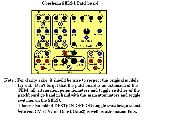
This is an example of a Patchboard using banana jacks which blends nicely with the main module layout.

Obviously, the patchboard dimensions will depend on the type of jacks and potemtiometers you are going to use. Hereunder, is another lay-out that you can use : the inputs are on the left and the outputs on the right.(Dimensions 9"x7.5" inches).

Alternative method
If you don't want to go through the hassle of constructing a patchboard, use the space ABOVE each module (long strip of steel frame where the ON/OFF AC Mains switch is located) and drill holes there : use mini-jacks or banana jacks to gain space.
If you never drilled through steel before ,don't do it yourself (the steel frame used by Oberheim was exceptionally thick): have it done by a professional drilling expert and make sure you have a few drill bits in reserve, just in case....
Enjoy...
Also, check Guidelines to construct a patchboard for the MS-1A Mini-Sequencer..