MiniAmp Repair & Modification

| HOME | HARMONICA AMPS | AMPLIFIED INDEX |
On this page:
* Most of this only applies to earlier models. Latest models have SMD components which is beyond the scope of most of this article, with the exception of the two sections indicated.
I got my first Danelectro's HoneyTone Mini Amp for practice, jamming, or performance. For a 1 Watt amp it's got decent tone, better than some of the other mini amps I've tried, in fact a better tone than a few valve amps I've tried. And it can get surprisingly loud - enough to jam in an average living room with an electric band at moderate levels. The volume, overdrive & tone controls give plenty of variety to it's sound. Add reverb or echo and it sounds big.
It's great for practice, busking, or jamming as it's very small and portable. The headphone jack is handy for practicing amplified mic technique quietly.
It's convenient compact size and light weight are also important
to me. It runs off a 9 volt battery (rechargables too) or 9 volt wall
adapter.
With the help of a 4mm stereo plug to 1/4" mono plug cable it can be used with a walkman as a very light portable mono boombox. You can also use the same cable from the headphone output into a PA or mixer to really get that great tone out to the audience at any volume level.
To make the cable you need a 4mm stereo plug, a 1/4" mono plug, and a length of single core shielded, coax audio cable. Wire both signals (ring and tip) from the 4mm stereo plug to the 1/4" jack's signal (tip).
I plug my Harp Commander and Reverb pedal into the HoneyTone, giving a lovely warm tone. I prefer the tone of this combination to the Crate VC508 I used to own. But even without the Harp Commander, it sounds like a little tube amp in it's own right. The jFET preamp plays a part in this.
For the price and size it's surprisingly good, and measures up against similar practice amps from other companies. Although I've heard good things about the the original Pignose, however it's a bulkier and heavier animal.
I recommend the HoneyTone to anyone who needs a small practice amp for any of the above reasons. It's a good mini amp, and I highly recommend it.
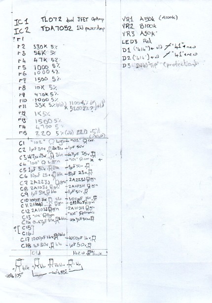
This is a schematic I made from my old HoneyTone,
I have no idea if the latest SMD model is the same or not.
I offer no guarantee to it's accuracy and take no responsibility
for the outcome of anyone using it.

| 1. Plastic block | 6. On/off switch |
| 2. Additional screw | 7. Earth strip for 3 pots |
| 3. O/drive 9mm POT A100k | 8. Battery clip |
| 4. Tone 9mm POT B100k | 9. 1/4" Speaker Out |
| 5. Volume 9mm POT A50k | |
| Before working on your HoneyTone: Disconnect the battery and power! | |
|---|---|
Rough circuit diagram & parts list.
Before working on your HoneyTone: Disconnect the battery and power!
When I was working with one of my HT's, I had the battery connected, but the power switch was off. The circuit board was loose and briefly brushed the back of the speaker zapping the power amp IC.
I had to find, purchase and install a replacement IC. If you need to
test things while the amp is in pieces, double check nothing can
accidentally touch any of the HT components. I've put cloth tape over
the back of the speaker, and insulated connections I've made to avoid further shortage. But always disconnect power before working on it!
I've found these amps can break easily if dropped on their head with a guitar chord plugged in. The case and components in themselves are sturdy enough. But there's a design flaw that means any impact on the 1/4" jack will push it into case, causing the circuit board to tear apart the overdrive & tone POTs and quite likely ruin the volume on/off POT as well.
The flaw itself is easily fixed by gluing in a small block of plastic or wood inside the case (diagram below), drilling a hole through it and the PCB, and securing the left side of circuit board into it using a self tapping screw making it a very robust unit.
The problem is the 1/4" input jack has a plastic thread which is easily stripped, easily done if you have a guitar lead plugged in and the amp is dropped on it's head from a height as little as a foot.
In addition there is only one screw holding the circuit board in place, and it's on the opposite side under the volume POT. So when the plastic thread gets stripped under the impact, there's nothing else to stop the circuit board being wrench away. Because the POTs are secured to the case as well as soldered into the circut board, they get ripped apart. So it needs support circuit board support under the existing jack.
1. & 2. When you look at the circuit board you'll see there's already a hole under the 1/4" jack, when assembled theres a little plastic nib located at the cross section of the lefthand strut. This offers no support, it merely helps hold the board in place when reassembling the amp. The new screw you're going to install will need a hole about 2mm up and left of that hole.

Disassemble the amp enough to safely take the circuit board out. Looking from behind the amp with the back off, theres a strut on the left side just below the 1/4" input jack. Take a small block of plastic or wood that is the same depth as the strut, and maybe a 1/2" x 1/4". And glue it on the strut so the it'll take any downward force. Super glue worked for me. Any epoxy should be just as good.
Now you need to make a hole through the circuit board and into the supporting block for the new supporting screw to screw into. When you drill the circuit board it's about 2mm left and up from the existing hole mentioned above. Check the other side of the circuit board before you drill through it! You don't want to drill through any important circuit tracks. With the two HoneyTone's I've done this to, both had only earthing circuit around this area which is fine. The diagram up and to the right shows about where you want the hole to go through the block you glued in. Near the top of the page is a photo of one of the amps I've fixed and modified.
Once you've made the holes, and everything is assembled, screw in a self tapping screw, like a Hohner handmade diatonic, Hohner MS diatonic, or Lee Oskar reedplate screw. Failing that a 2M or imperial size 2 screw less than 8mm or 5/16" in length. If the screw is not self tapping you'll need to find a way to tap the hole. It's easy enough to purchase a tap and pinvise from McMaster & Carr.
If you have been unfortunate enough to have already dropped yours and it's no longer working, then you're going to have to do a bit more work...
Replace the POTs
3. 4. & 5.
The photo near the top shows you the POTs you'll need to replace. All
three POTs I used are single gang 9mm square variety, type A are
logarithmic, and type B are linear. I used A50k (type A 50,000 ohm) for
volume (in addition to an on/off switch, modification 6
.), B100k (type B 100,000 ohm) for tone, but I only used an A50k POT
for overdrive. It gives me about 3/4 range of overdrive than the original
A100k POT, but thats more than plenty for harmonica, leaving you more
headroom to play around with. The overdrive POT only needs two
connections, looking at the component side of the circuit board, the left
and center holes are connected and are wired to middle POT pole, right
hole connected to the right most POT pole. Volume and Tone need all
three connections.
I recommend using lengths of insulated wire about the length of your thumb to connect the POTs to the circuit board. Solder each wire to each pin of the replacement POT, then gently bend all three pins pointing down, and insulate the exposed pins. I found the most effective insulation is with a hot glue gun, which is very cheap. Hot glue also offers some flexible support to the wire's connections reducing the chance of breakage with a lot of movement. Face the POT's pins (and wire) to the circuit board (same as the original POTs), and solder in each of the POT's wired connections. When you go to reassemble the amp, twist each POT 180 deg, so that the POT's connections are facing the rear of the amp.
Installing the additional screw to secure the circuit board, and replacing all the POTs in this manner, will make the amp impervious to any further internal damage. As for the on/off switch (modification 6.) I much prefer it to the original setup.
The shanks of the replacement POTs I used are not the same as the originals, so the original silver plastic knobs do not fit. I replaced all of the knobs on both HoneyTones with a black plastic screw on knobs. They have a little screw at the back which you tighten them to the shank with, meaning they can fit to most POT shanks of this size, including the original HoneyTone POT's.
6. If you replace the original volume dual purpose POT with on/off built into it, then you'll probably need to install a seperate switch. Even if this isn't the case, I personally find it better being able switch the amp on and off without changing the volume. The only possible downside is when the volume is up, and you turn it off, there's a pitiful little squeak.
Install it as shown in the picture below. Inside the case there's an indentation running front to back, and the LED hole is centered to this. Using a pencil, mark a spot centered on the indentation, for the on/off switch hole. The switch I used required a 5mm hole, so I marked the middle point 5mm in from the inside edge of the case where the indentation stops, or 8mm from the outside edge.
I ground off most of the length off the top of the switch, leaving it with about 5mm length above the hex nut. Then rounded it off and polished it smooth using a rotary tool with a grinding bit, and shofu brownie. When I reassemble it into the case I have it so it's on position has it swung back towards the back of the amp. This is so it doesn't get in your way when adjusting the volume while the amp is on.

7. After replacing the POTs, if you don't want your HoneyTone to
hum, you'll need to ground all three POTs. Danelectro's approach is to use a length of stiff wire soldered across the top all three POTs and
wired to the ground of the on/off connection. I found this approach
difficult with the 9mm square POTs.
 Instead cut enough length of 0.001" feeler stock (available at McMaster & Carr) to reach
over the three holes where the POT shanks go through, with a bit extra to
spare. Work out where the POT's shanks fit, perforate holes wider than
enough to fit over the POT's shank threads. Cut a length of wire to
ground the feeler stock, about 100mm/4" is enough. Strip enough
insulation off both ends to be looped back and soldered to itself. Loop
one end through one of the sides of the perforated holes back onto itself
and solder, I found it tough to solder wire to feeler stock. Then ground
the other end by looping it around the negative/Cathode/left leg of D3
Diode (green arrow in image), and solder in place.
Instead cut enough length of 0.001" feeler stock (available at McMaster & Carr) to reach
over the three holes where the POT shanks go through, with a bit extra to
spare. Work out where the POT's shanks fit, perforate holes wider than
enough to fit over the POT's shank threads. Cut a length of wire to
ground the feeler stock, about 100mm/4" is enough. Strip enough
insulation off both ends to be looped back and soldered to itself. Loop
one end through one of the sides of the perforated holes back onto itself
and solder, I found it tough to solder wire to feeler stock. Then ground
the other end by looping it around the negative/Cathode/left leg of D3
Diode (green arrow in image), and solder in place.
When you're ready to reassemble the amp and push the POTs through the
case, you put each one through the feeler stock, then through the case -
when you bolt each POT to the case this will push the feeler stock home
snuggly.
8. The early original HoneyTone battery compartment had two metal strips installed into the casing, and you simply slid the battery into place. The problem with this is the clips become loose and fail to make a reliable connection The fix requires a 9 volt battery clip which you can get from a local electronics store like Radio Shack, Dick Smith, Jaycar, or similar.Inside the HoneyTone disconnect the red and black wires from the metal clips, a pair of sidecutters is probably the easiest approach. Solder these to your new battery clip, and insulate the connections with heat shrink, insulation wire or glue from a hot glue gun. Doing things this way gives you ample wire between the clip and the PCB which makes life easier. Although it's preferable that this doesn't run alongside the speaker wires.
Remove the original clips from the battery compartment. To fit the new battery clip in, the plastic frame work that held the original metal clips in place needs to be cut and ground out, and a hole is needed to fit the clip through into the compartment. I used a metal burr on a Dremel to cut away the bulk of unwanted plastic, and a file to finish cleaning it up. A drill can make life a bit easier to create a hole for the clip.
Having done this, the clip I bought was relatively thin, and the battery tended to rattle about inside the compartment, which was irritating, so I took a wood tongue depressor, like what the doctor uses, and used double sided sellotape to stick it to one end of the compartment to hold the battery in place. An iceblock stick will serve just as well.
It's interesting to note the HoneyTone amps issued since then now come with this setup.
9. Adding a 1/4" jack Speaker Out will enable the HoneyTone to
drive any 8 Ohm speaker cabinet directly, just like the
Smokey Amp.
There are some precautions you must take into account when you use this
output:
 You'll need a 1/4" jack that can be screwed into the back of the
HoneyTone casing. Make sure you get a 1/4" jack that has two signal
tabs. The sort that will allow signal straight through from one tab
to the other while nothing is plugged in. And when plug is inserted,
redirects the signal to the plug tip instead.
You'll need a 1/4" jack that can be screwed into the back of the
HoneyTone casing. Make sure you get a 1/4" jack that has two signal
tabs. The sort that will allow signal straight through from one tab
to the other while nothing is plugged in. And when plug is inserted,
redirects the signal to the plug tip instead.Drill a hole in the back of the case where it says "Made in China", install the jack, and reassemble your HoneyTone.
While an 8 Ohm load is plugged into the 1/4" speaker output, the HoneyTone's speaker shouldn't make any noise. Whenever you want use the speaker output, turn the amp off. Connect it up, double check everything, making sure the 1/4" plug is wired into an 8 Ohm speaker, power soak set to 8Ohms, or appropriate DI box with attentuation turned on, BEFORE you turn the HoneyTone on.
Using this modification, I've used the HoneyTone directly into the speaker of a Fender Blues Junior Black Face combo amp, and got a surprising amount of volume with a nice full warm tone. After doing this the BJ owner spent the next couple of hours trying to get something as warm using the BJ amp proper. :-)
10. In my opinion this is a very important modification.
As my harmonica technique improved, I discovered that my HoneyTone would abruptly produce a nasty distortion, it became a common and very tedious aspect. I quickly realised I had to figure out how to fix this. In the interum, I found I could use my Dan Echo in front of the amp to avoid the problem, but it sort of defeated the point of having a small light portable practice amp I could quickly plug into and play through anywhere anytime. My HoneyTones didn't get much use for quite some time until I figured out how to fix it.
The symptom, I learnt, was the result of the OpAmp, the ubiquitous TL072, reaching the limit of the voltage supplied to it, once it hits that limit it all goes pair shaped. I had two avenues to explore. Find a way of keeping the mic's signal low enough to avoid the problem, after all electric guitars apparently don't have this problem with 9 volt opamp circuits, nor do weaker microphones. Failing that, find a way to increase the voltage supply. The In Addition section on this page covers my experiments. Bottom line, the solution that worked for me is to substantially increase the voltage supply to the TL072, while still just using one 9 volt batery, or plugging in a 9 volt adapter. The key to which is the MAX1044, an unassuming little 8 pin IC.
In the description below, all references to the HoneyTone circuit
board, assume it's installed in the HoneyTone, looking at the
component side. References to R12, C13, D2, etc are the component
labels on the HoneyTone circuit board.
You can purchase MAX1044 ICs from
Banzai,
their international postage rates from Germany are very
reasonable.
The MAX1044 +9/-9volt circuit itself is very simple
http://www.geofex.com/circuits/+9_to_-9.htm (top diagram
on that page), with big thanks to R.G.Keen.
The circuit shows a switch between pin 1 and pin 8 - if you leave this
open, it produces a loud high pitched tone into the amp, which fluctuates
in frequency as you play, and it's very unpleasant.
By shorting these two pins, it multiplies the frequency by 6, raising
the pitch well above normal hearing range, essential for the
HoneyTone.
What you need is: the MAX1044; I always install an IC socket, so the
IC's pins don't have to be soldered; a pair of 10uF capacitors; something
to wire it all together on, I used a 7/8" by 1/2" section of project PCB
(perferated holes connected by rows of track); and three insulated leads
for +9 volt, -9volt, and ground.
Ground can be wired to a ground strip anywhere on the HoneyTone circuit
board, I connected it to the track right of R3. The +9 volt supply needs to be wired to the 9 volt track after the on/off switch, the right leg of R12 resistor that sits just above the TL072 is connected to this track.
Finally the negative voltage pin 4 of the TL072 is wired to a ground track, which needs to be disconnected from that track, and rewired to the -9 volt lead of the MAX1044 circuit.
What complicates this is capacitor C13's top leg is connected to that same bit of ground track as the TL072. I've cut the track both sides of pin 4. Used a short bit of insulated wire to reconnect C13's top leg to a ground pin of another component, the right leg of D2 for instance. Then connected TL072 pin 4 to the -9 volt lead of the circuit. Done!
Even though the above works well, I went one step further with my first HoneyTone. R12 lowers the voltage from the 9 volt battery/adapter, which then goes on to feed the TL072 and other parts of the circuit. I use rechargable NiMH batteries, most of mine peak at 8.60 volts fully charged, it's only recently I've been able to get ones that give the full 9 volts. Since the TL072 can handle up to 18 volts, I didn't see why it needed a lowered voltage. I know the reason they designed it that way was to reduced drain on the battery, but since I want to make sure the opamp is getting enough voltage to handle the mic's input, even when the battery is getting low, I decided to do away with this on my first HT.
It meant cutting the track both sides of TL072 pin 8 (positive volt), reconnecting the left lead of R12 to either the top leg of R4 or the right lead of C10. And connecting TL072 pin 8 to the 9volt source, same as the +9 volt source used for the MAX1044 circuit.
For myself, when wiring the MAX1044 circuit to the HoneyTone's circuit board, I drilled through tracks I wanted to connect it to from track side of the pcb, scratched away the protective layer of the track around the hole, poked the appropriate wire through the hole from component side, and soldered it to the track.
With my first HT, I've used a hot glue gun, 2x 2-56 round head screws, and 2-56 nuts to create a mounting in the recess of the case on the left below where I've added the additional mounting screw for the HT's circuit board.
With my second HT, I found a couple of PC motherboard mounting hex stands with threads and nuts. I drilled holes in the pcb (after installing the components), installed the two hex stands, applied glue to the bottom of the hex stands, placed it in a similar place to my first HT, waited until the glue set, undid the nuts, gently removed the PCB, then secured the hex stands in place using my hot glue gun, looking very tidy once it was all done. I've temporarily installed a DPDT switch, so that I could switch the modification in or out. The 9 volt wire from the HT's PCB is wired to one pole, the wire connected to TL072 pin 4 to the ohter pole. When the switch is in the "out" position, the 9 volt wire is disconnected, and the TL072 pin 4 wire is connected back to ground. In the "in" position, the two wires get connected as per the above description. Make sure the ground connections of the MAX1044 circuit is always connected to the HT's ground.
What's the point of all this?
* I get a lot of enjoyment out of my HoneyTone amps. For what they are,
they sound good, because they use good ICs. I believe the TL072
jFET Op Amp is the reason why they have better distortion than some of
the other mini-amps I've tried. I've since learnt the HT's TDA7052 1Watt
power amp is close in design to the TDA7051 power amp used in some studio
quality mixers.
* I want to learn about amplifier and audio electronics, I learn by
doing. By reverse engineering the HoneyTone design, and by working out
how to repair or improve it, I'm learning a great deal. The risk of
damaging my HT is inexpensive, and I learn even more by fixing my
mistakes.
* I like to share what I've learnt, so others may benefit from it. I'm
certainly glad when I find a website where someone shares what they know
on a topic I wish to learn about.
Dec 2006 - I've built a 22Watt speaker cabinet. Made using a wood Lindauer wine box, and six speakers: four 4Ohm 3Watt speakers salvaged from two sets of busted multimedia speakers; and two 8Ohm 5Watt speakers from a local electronics shop. It sounds great, much better than the HT's internal speaker, but not as big a sound I've got through a Fender Blues Junior speaker.
7 Jan 2007 - I've changed the instructions for modification 7. wiring the replacement POTs grounding strip. I initially grounded it to the negative terminal of the replacement on/off switch, this however carries the full 9 volts from the power source. So the new instructions show how to connect to the amp's ground.
* - A while ago, I discovered I get nasty clipping distortion when using any decent powerful microphone straight into the HoneyTone, and cup it to get a ballsy tone. Not pleasant. If I use my modified DanEcho in front of the amp, I have no such problem. So I'm working on a modified circuit based on Juergen's Dan Echo modification, but substituting the opamp he recommends with the jFET Op Amp model TL072 used in the HoneyTone. I'll update this page when I have something to report.
* - I've replaced the 1/4" input jack of my older HT, with an internal open 1/4" jack with metal thread. Very solid result. However it's introduced a low hum, which turns into a squeal if volume, tone and overdrive are turned right up, and nothing is plugged into the input. I've temporarily installed a 1uF capacitor from the signal in of the new input jack, so it no longer squeals by itself, however if I touch the headphone output it howls. I suspect it's to do with the way I've wired the signal lead from the new 1/4" jack. So I'm going to learn how to fix it.
10 Feb 2007 - Developments:
* - I made a voltage follower for my HoneyTone, it did nothing
for the clipping, and as tone suck was never an issue it changed nothing
else. I tried it wired into the HoneyTone's 9v rail, then tried it with
it's own seperate battery. I've since removed it.
From what I've gathered to date, the clipping is due to the hot microphone causing the OpAmp to draw more power than it has available, there is a resistor between the 9volt battery and the TL072's +ve leg. I have another simple class A preamp with a similar OpAmp without such a resistor, so it's running on 9volts - it too clips, but I have to play harder into the mic to make it happen. Still very annoying to put it mildly.
The next step is to learn how to make a limiter, and try that.
A limiter allows a signal to go up only to a certain level, and not
beyond that.
Another approach which will require some major changes is running the
TL072 with a higher voltage supply as it can take up to 18volts. So I'd
set the amp up to allow a second 9 volt battery in series, and install a
pair of voltage regulators (9volt and a higher voltage for the TL072 VCC
pin). If that works, then I'd need to get an 18 volt adapter to run it
off. However, I suspect the voltage to the OpAmp was reduced to
limit the output level into the TDA7052 1Watt power chip. If I up the
power, it could cause nasty distortion further on down the chain.
* - I've figured out what was causing the squeal and hum. The
original HoneyTone 1/4" input jack is setup to short signal to earth when
nothing is plugged in. I replaced the internal open 1/4" socket with the
same sort used for the speaker output jack mod described above. I wired
it so when nothing is plugged in, signal is shorted to earth until you
plug something in. So without that signal short, the hum and squeal is a
"design feature" of the HoneyTone.
UPDATE Putting 450kOhm resistor on the input, to lower the signal to
stop clipping, introduces resistance to the "short circuit" when
nothing's plugged in, meaning it will squeal if set up that way.
Added comment: 450kOhm reduces the volume dramatically and is unsatisfactory.
* - The headphone jack of my old and tattered HoneyTone is faulty, causing intermitant silence when using the speaker. So I'm going to have to replace that too. In the meantime I've mitigated the problem by using a hot glue gun to secure the component on the PCB, but it's not reliable.
18 Mar 2007 - Developments:
* - Built a jFET buffer which did absolutely nothing to the tone/sound or clipping.
* - Build a discrete jFET preamp which also did absolutely nothing to the tone/sound or clipping
Oh well, at least now I know I can build buffers and preamps that are clean, clear and work transparently which will be useful for some unrelated projects.
* - Rewired the TL072's positive power pin so that it gets all 9 volts from the battery, as I suspected it reduced the amount of clipping, but if I blow hard enough it's still there - this puts it on a par with my bARCUS bERRY preamp.
* - Received an email from a fellow HoneyTone owner who had connected his HT up to a series of D type batteries, and he didn't get any clipping. He's since written back to say he's wired up 2 triple AA battery holders which he's stuck to the bottom of the amp and very happy with. I certainly appreciated the reports because now I know putting more juice through the amp won't kill it!
* - I wired a 9volt battery and 4xAA batteries in series into
the HoneyTone giving it around 13volts. All the batteries are NiHM
rechargables. There was still a little bit of clipping if I really
pushed things. When I put a jFET buffer, with the signal rebiased to
+4.5v in front there was no clipping at all, the same buffer without the
signal bias allowed the HoneyTone to clip a little.
This successfully proved to me the clipping goes away with more power.
However I'm not comfortable running the entire circuit on more volts than
it was designed for. Also I regularly use wall adapters with both my
HoneyTones, and don't feel like forking out for higher voltage adapters.
What's more I'm working on some other projects which I want to run off 9v supplies. Besides there are plenty of pedals and products out there than run off 9volts and don't clip when used with a bullet mic, I don't see why this can't be solved. So now I'm going to target the TL072.
* - I wired a second 9volt battery with the positive terminal to the HoneyTone ground/common, and connected the TLO72's negative supply pin to the negative terminal of the second battery, effectively giving it a -9v rail, supplying the chip with around 17volts. The rest of the HoneyTone circuit is untouched. It worked great!
But I still want to see if I can find a way to solve this using 9volts. I've found a circuit showing how to make +/-9volt power supply using only one 9volt battery (or 9vDC adapter), using a charge-pump-convertor IC, MAX1044. I'll have to order it from an online store.
There is one consideration, if this approach works. The top operating voltage for the TL072 is 18volts, and the datasheet lists typical operating voltage at 11volts. As I've found, less than 13volts isn't going to cut it, but I don't want to feed it 18volts either. I'll need to work out an appropriate resistance on one of the supply pins to keep the total voltage supply down.
* - With the TL072 now getting the full 9v from the battery, I
found I can use a 320kOhm resistor in front of the HoneyTone to stop
clipping, rather than 450kOhm. Meaning it's louder than it was when I
first tried this. I've also learnt how to increase OpAmp gain.
The HoneyTone's overdrive control is a good example, it's a variable
resistor which controls the amount of negative feedback of the first
OpAmp stage. The higher the resistance, the less (signal cancelling)
negative feedback, the more gain you get. That's why the lower value POT
I'm using can't create as much overdrive.
With a lower resistance at the input, I might be able to increase the
TL072's gain enough to compensate. One side effect of this, is it may increase hiss, if it does, a low pass filter may fix it.
R11 controls the second opamp stage's gain. I'm considering
removing it, soldering a pair of single pin IC sockets into the PCB where
the resistor was, and then test it out with a POT to find a
resistance that works well, and install that resistor.
The drawback is, as you know, putting a resistor in front of the Opamp
(to reduce the input signal) creates hum and squeal when nothing is plugged into the amp - I'd prefer to avoid this.
For now I'll wait until I've tried the MAX1044 circuit - it'll be easier to make and fit, than modifying the HoneyTone's circuit, or making a limiter/compressor circuit.
19 July 2007 - Success!
The MAX1044 works!
Using 9 volt battery, or adapter as per the original design, and inserting the circuit, it works perfectly, same volume, no nasty clipping, just beautiful smooth distortion. The only possible trade off is slightly quicker battery drain. Instructions above
modification 10.
I'm very happy with the end result.
Final comments
Well, this marks the end of my HoneyTone projects. I've learnt quite a lot about audio solid state electronics as a result. My soldering skills have improved a great deal. And my faith in jFET based opamps instated and steady.
I now have several future electronic projects, and have already purchased all the components for the job. From all this I've got ideas on building a louder practice amp, using a more powerful amplifier IC than the TDA7052, which come in either mono or stereo.
For quite some time I intended to build low powered tube amp heads with a dummy load and line out. However I've learnt a great deal about the characteristics of overdrive, distortion, and amplifier tone. I've spent many hours on the internet, searching, reading discussions, listening to various sound samples by many musicians using all sorts of different setups, and such. I've decided to build a number of solid state effects using opamps and/or discrete jFETs, and different types of diodes, for tone stacks, clipping, overdrive, amplifier simulation, and cabinet simulation. Time will tell whether the end result will satisfy what I'm looking for.
 Buy yours from Coast to Coast |
Buy yours from Amazon |
| HOME | HARMONICA AMPS | AMPLIFIED INDEX |