The weird ascent of the lunar module

 A video of the Apollo 17 video library shows the lift-off of the ascent module of Apollo 17 supposedly returning to the command module. All the moon hoaxers have found to say about this video is the absence of the engine's plume, to what the Apollo believers think they have an answer. Yet, there is much more to say about this video, and this is what this document is going to explain. |
 Initially the spaceship is moving in the direction that the camera is filming. We can wonder why the operator waited for so long before raising the camera. The shift between what the operator sees and what actually happens is 1.25 seconds. There is a delay of 2.5 seconds between an action of the operator on the camera and the corresponding result he sees (the time to send the command plus the time for the corresponding result to come back). The LM took more than ten seconds to reach the top of the screen after the lift-off, so the operator had all the time to act on the camera before the LM would reach the top of the screen. By waiting for the LM to reach the top of the screen before reacting, there was a chance that the LM would get out of the field of view of the camera. |
 In the first phase of the ascent, as the LM is going in the direction that the camera is filming, we see it pitch quite abruptly. In fact it should not pitch that way, it should pitch very slowly, regularly.  When the Saturn rocket is raising in the air, we never see it pitch that way, it pitches very slowly, progressively; if it had pitched like we see the lunar module do on the video of its ascent, it would have fallen back on earth and crashed on it.  This simplified schematics illustrates what happens when a rocket is launched. I have represented the rocket's thrust with a yellow arrow, the gravity with a red arrow, and the gradually appearing centrifugal force with a green arrow. When a rocket is launched to be put in orbit, it first ascends vertically to extract itself from earth's gravity and gain vertical speed. Then it starts turning to a more horizontal attitude to start gaining horizontal speed, but not brutally, very gradually instead. It first takes a moderate horizontal attitude which allows it to gain horizontal speed. As it is gaining horizontal speed, a centrifugal force starts to appear, and this centrifugal force helps the rocket to counter earth's gravity. So the rocket turns a little more horizontal, which allows it to gain still more horizontal speed; as the horizontal speed increases, so does the centrifugal force, which helps more the rocket to counter earth's attraction, which allows the rocket to turn more horizontal to gain still more horizontal speed, and so on... At the end of the process, the rocket ends in a completely horizontal attitude; its horizontal speed is now the orbital speed which allows to create a centrifugal force which is exactly equal to earth's attraction, which means that the rocket has no more to give a vertical force to counter earth's attraction. The rocket can keep its orbital speed without having to produce a horizontal force, for, in the void, there is no resistance force to slow down the rocket. The rocket can naturally follow its orbit without having to use its engine. The change of attitude of the rocket from vertical to horizontal is very slow, progressive, and regular, it can in no way be brutal.  If the rocket, after its initial vertical ascent, was brutally turning to a horizontal attitude, as it has not gained the horizontal speed allowing to produce a centrifugal force which counters earth's attraction, it would start to fall back to earth. As it is falling down, it would gain horizontal speed, but not fast enough to have reached the necessary centrifugal force allowing to counter earth's attraction before it hits the ground. The crash is inevitable.  The physics of the ascent is exactly the same for the lunar module. It has to turn slowly and regularly to a horizontal attitude to leave the time to the centrifugal force to grow enough to be able to sustain the lunar module in space.  After the pitchover of the lunar module, we see the lunar module start to fall, which is normal, since the lunar module hasn't yet acquired the horizontal speed which would allow to create a centrifugal force compensating the lunar attraction; but, suddenly, this fall mysteriously stops; what is this mysterious force which is stopping the fall of the lunar module, since the centrifugal force allowing to compensate the lunar attraction still doesn't exist? |
Then, all of a sudden the lunar module starts to make a strange sinusoidal move. Some Apollo believers have retorted that the sinusoidal move that the lunar module was making at the end of the video was coming from the efforts of the operator to follow the lunar module with his handcontroller, but this explanation cannot stand, and I am going to explain why. You can see that the horizontal axis of the sinusoidal move is not on the middle of the image, but near its bottom. |
 It is obvious that the operator, if he is not completely dumb, would try to center the lunar module on the middle of the image; if he can see that the lunar module is under the middle of the image, he would move the handcontroller down, and not up, and conversely, if he can see that the lunar module is above the middle of the image, he would move the handcontroller up, and consequently we would see something like this... |
 ...and not like this. On the video, even when the the lunar module is under the middle of the image, the operator would make it move down instead of up, he would never try to reach the middle of the image, which is totally illogical. I can't believe that NASA would have let a completely dumb operator operate the handcontroller, who would not know that, when he sees the lunar module under the middle of the image, he must make it move up on the image and not down! |
 In fact, if really the lunar module was going straight and not swaying, we should have seen something like this. Indeed, after having made a maneuver on the handcontroller, the operator knows that he will not immediately see the result, and must wait for the delay of the command (2.5 seconds); the next maneuver depends on the place he will see the lunar module after the delay of the command; if he sees the lunar module above the middle of the image, his next move will be a move down, and, if conversely he sees the lunar module under the middle of the image, his next move will be a move up; moreover, if he is normally skilled, he should manage to get the lunar module closer and closer to the middle of the image, and his moves on the handcontroller should be smaller and smaller. The move of the lunar module on the image would look like a square wave, centered on the image, and with a decreasing amplitude... |
...and not like a sine wave, not centered on the image, and with an increasing amplitude! It is doubtless that the sinsoidal move that we see the lunar module make on the video comes from a swaying move of the lunar module. What what does cause this sinusoidal move? |
 In fact there is a confirmation that the weird behavior of the lunar module does not come from the actions of Ed Fendell on the handcontroller as he tries to follow the lunar module on the screen, and he has some difficulties because of the delay between the command and the result he sees on the screen. Indeed, here is what Fendell has explicitly said: "Now, the way that worked was this. Harley Weyer, who worked for me, sat down and figured what the trajectory would be and where the lunar rover would be each second as it moved out, and what your settings would go to. That picture you see was taken without looking at it the liftoff at all. There was no watching it and doing anything with that picture. As the crew counted down, that�s a Apollo 17 picture you see, as Eugene Cernan counted down and he knew he had to park in the right place because I was going to kill him, he didn�t � and Gene and I are good friends, he�ll tell you that � I actually sent the first command at liftoff minus three seconds. And each command was scripted, and all I was doing was looking at a clock, sending commands. I was not looking at the television. I really didn�t see it until it was over with and played back. Those were just pre-set commands that were just punched out via time. That�s the way it was followed." Link to the explanation of Ed Fendell So, no, the explanation of the Apollo believers does not stand, Fendell was not looking at the screen, he was just applying preprogrammed actions at definite moments. It means that, if the lunar module was behaving that way on the video, it's because it was really behaving this way in space. |
 The center of mass of the space ship cannot remain constantly aligned with the line of thrust if the engine is not reoriented; as the propellant tanks are emptying, the center of mass shifts, and it is no more aligned with the direction that the engine pushes; the consequence is that it would create a misalignment torque if the engine was not reoriented so that the center of mass becomes aligned again with the line of thrust. The engine of the descent stage was gimbaled, which was allowing to make it swivel it along the descent so that the line of thrust remains aligned with the center of mass as this one shifts because the propellant tanks are emptying. |
 But the ascent engine was fixed and not gimbaled like the descent engine, and thus it could not be swiveled to keep the alignment with the center of mass. As long as the center of mass was aligned with the line of thrust, everything was OK. |
 But, after the propellant tanks had started emptying, the center of mass was progressively shifting, and the consequence is that it was creating a misalignment torque which was making the lunar module turn clockwise and pushing it on the right. If nothing was made to counter this misalignment torque, the lunar module would start into a fatal pirouette, and would end up crashing on the moon. |
 Since the ascent engine could not swivel to catch the realignment with the center of mass, the solution was to use the lateral thrusters of the RCS to create a counter torque which would oppose to the misalignment torque. If the torque created by the lateral thrusters could be exactly equivalent to the misalignment torque, the lunar module could keep going straight. But the lateral thrusters could not be throttled, they were working in "all or nothing", and consequently it was not possible to adjust their thrust so that they would create a torque exactly equivalent to the misalignment torque. The consequence is that they could not be permanently fired, but periodically instead; and as they could not be activated at a sufficient frequency (the guidance period was 2 seconds), the result is that it was not possible to avoid a consistent swaying move. |
 This animation explains what was happening: The misalignment torque was making the LM turn clockwise and go right; then the lateral thrusters were fired, and were making the LM turn counterclockwise, and go left; then the lateral thrusters were shut off (otherwise they would go on making the LM turn counterclockwise and go left), and the misalignment torque was making the LM turn clockwise and go right again, and so on. The more the misalignment torque was strong, and the more the amplitude of the oscillating move was consistent, for the frequency of command of the lateral thrusters could not be increased to counter the misalignment torque faster. This could work as long as the misalignment torque was not greater than the counter torque created by the lateral thrusters, for, if ever it was becoming greater, this would be fatal to the LM, and there would be nothing it could do to avoid a fatal issue, apart from shutting off the main engine, but this too would be fatal to the LM, for it would then be incapable to reach its orbital speed. |
 When we see how the main engine was placed, it appears that the center of mass was not aligned with the engine's thrust when the propellant tanks were empty; however, when they were full, the balance was possible because the propellant closer to the main engine had a higher density than the excentered propellant. But, as the tanks were emptying, the center of mass was progressively shifting right, and a misalignment torque was then appearing. This is absolutely not a supposition I am making, this is confirmed in the documentation by the NASA engineers. Even Clavius is talking about it on his site, and saying this: " As the off-axis thrust caused the ascent stage to rotate, the RCS jets fired to counter the rotation and return it to the correct attitude. This is why the films of the LM ascent seem to show a periodic sway or oscillation: the RCS "fought" the off-axis ascent engine." |
 The fact that the tank of the oxidizer is placed closer to the ascent engine is explained by the fact that the oxidizer has a greater density than the one of the fuel (1.5 times greater). If they were placed at the same distance, the difference of density of the propellants would make the LM turn on the side of the oxidizer tank. At the beginning of the ascent, when the tanks are full, their contents are heavier than the containers, so the misalignment torque is limited. But, as the tanks are emptying, the difference between the contents and the containers decreases, and consequently the center of mass of the LM shifts toward the fuel tank, with the consequence that the misalignment torque increases; as the lateral jets of the RCS cannot increase their frequency of correction of the misalignment torque, the consequence is that the amplitude of the oscillation of the LM progressively increases. (The purpose of this animation is to make understand what happens and not to represent the exact reality). Even if it was possible to correct the misalignment torque with the lateral engines, it still was uselessly wasting their propellant (and complicating the guidance, for they are also used to modify the trajectory of the LM), whereas this propellant would have been saved if the ascent engine had been gimbaled. |
 If you observe the sinusoidal move of the LM as it goes left, you can see that the amplitude of the sinusoid tends to consistently increase. You can see that, when the LM is about to leave the field of view of the camera, the amplitude of the sinusoid is already consequent compared with the size of the lunar module! And we only see the first seconds of the powered ascent, which is still going to continue for several minutes. If the amplitude is already quite important after only some seconds, you can easily imagine what it will be after several minutes! There is a non negligible chance that the misalignment torque ends up being bigger than the counter torque created by the lateral thrusters, which would reveal fatal to the LM. Also notice that, when we see the sinusoidal move appear, it already has some amplitude, whereas it should start with a small amplitude. |
 The rover is placed to look at the back of the lunar module. The lunar module always lands to have the sun in its back, and to have its front in the shadow. It is a natural way of landing, for the lunar module always comes from East (the command module is orbiting the moon clockwise), but it also allows the astronauts to get out of the LM without being exposed to the sun. So the front of the LM is directed toward the West, and its back toward the East. When the rover looks at the back of the LM, it is consequently looking toward West. And it is logical that the rover looks toward West, for the lunar module must go mostly West. |
 The lunar module, in order to join the command module, must, like the command module, orbit the moon horizontally clockwise; so it had to go West. As the landing site of Apollo 17 was a little North, the lunar module also had to go a little South to get closer to the moon's equator, but not brutally, by making a long curved trajectory. |
But this is not at all what we see it do; intially the lunar module is going in the direction that the rover's camera is filming, toward West. |
Then the lunar module makes a brutal quarter of a turn, which means that it is now going straight South. |
 So, this is the trajectory that we see the lunar module take on the video. The lunar module is not at all taking a horizontal orbit to join the orbit of the command module, but a vertical one instead. |
 It means that, when the lunar module crosses the orbit of the command module, it will cross it in perpendicular, and will not go in the same direction that the command module does. And, at the speed that the lunar module crosses this orbit (around 6000km/h), it is totally incapable to turn of a quarter of a turn to go in the same direction that the command module does. And if you ask if, instead of making this brutal impossible turn, the lunar module could not make a very large turn to join the orbit of the command module, I'll say that it would cost much more propellant of the RCS to make this turn, even a very large one, than if the lunar module had done things normally, i.e. take a horizontal orbit from the start (and in the technical document, there is no question of doing this type of maneuver). And the RCS is already wasting much propellant to counter the misalignment torque! |
 Especially since the RCS will also need to have propellant left to make the final maneuver to dock at the command module. Anyway, with all the propellant that the RCS has wasted, it will not even reach the orbit of the command module. |
 Moreover, you can see that the amplitude if the sinusoidal move is already important on the video of the ascent of Apollo 17, and steadily increasing; yet, this video is only a half minute long, and the powered ascent lasts for more than seven minutes (according to NASA documentation). So, if it is already that important after a half minute, you can imagine what it will be seven minutes later! It is more than probable that the lunar module will meet a fatal fate, and will end up crashing on the moon. You see, that there is much more than the absence of the engine's plume in this ascent! |
 Now, when we compare the video taken by the rover's camera with the one taken by the DAC camera inside the lunar module, at the moment that the lunar module shows a sinusoidal move on the video of the rover's camera, we see none on the video taken by the DAC camera. The Apollo believers take it as a proof that this sinusoidal move does not come from the LM itself, but from the effort of the camera operator to center the LM on the screen, though it is completely illogical, and would show a rare incompetence from the camera operator. |
 But, on the first phase of the ascent, we see the lunar ground move very importantly on the video of the DAC camera, like the LM was pitching in a consistent way, while, meanwhile, the LM only shows a moderate pitch on the video of the rover's camera; and, when we see the LM make an important pitch on the video of the rover's camera at the end of the initial phase, the lunar ground moves much less than previously on the video taken by the DAC camera, like the pitch was reduced at this moment. In other words, the LM pitches importantly on the video of the DAC camera when it pitches moderately on the video of the rover's camera, and, conversely, it pitches moderately on the video of the DAC camera when it pitches importantly on the video of the rover's camera. There is a total contradiction between the two videos, they are not synchronized with each other. At least one of the two is fake, and guess what? They are both fake! |
 Later, on the video taken in the lunar module, we can see an irregular move of the lunar module which comes from the swaying move of the lunar module, and this swaying move is also increasing. So the swaying move arrives later on the video taken in the lunar module, and is not synchronized either with the video taken from the lunar rover. |
 Now, to come back to the absence of the engine's plume, the Apollo believers think they have the answer for it. Michael Shermer gives this explanation for the fact it is not visible: "the main reason is that the lander�s engine used hypergolic propellants that burn very cleanly" Oh really? |
 Then, why can we see the plume of the lateral thrusters on a sequence of the film of the camera of the command module, while they use the same propellant as the ascent engine? |
If we can see the plume of the lateral thrusters, there is no reason why we should not also see the plume of the ascent engine! |
 There still are some weird facts, though not as incriminating as what precedes. We see some weird colored sparkles quite far from the lunar module, like these two ones I have circled on this image extracted from the video. |
 Or these two ones on another image extracted from the video. Even though these are minor facts compared with the previous ones, they still raise questions. |
 Apollo 17 is of course not the only mission in which there are anomalies in the ascent of the lunar module, since all of them are fake. In this video I am going to show problems in the ascent of the lunar module in Apollo 16 and Apollo 15, though there is much less to say than in Apollo 17, so this video will be shorter. |
 This is what the camera of the rover sees shortly after the lunar module has lifted off from the moon in Apollo 16. We see the lunar module slowly regularly come down, then, when it is close to the bottom of the image, it suddenly goes up again, because the camera operator has lowered down the rover's camera to go on following the lunar module in its descent. In its descent??? |
 After the lunar module has lifted off, it is going to climb up in the lunar sky to reach an orbit around the moon, in a first phase called "powered ascent", in which it will intensively use its engine. After it has reached the parking orbit, it will begin a second phase to reach the orbit of the command module, in which, most times, it will not use its engine, only occasionally. If the rover's camera wants to follow the lunar module, it will have to be regularly raised, so not to lose it from its field of view. Each time the lunar module comes near the top of the image, the camera operator raises the camera, which has for effect to bring the LM near the bottom of the image, so the camera can go on following the lunar module which is going to go up again on the image. |
 But, it is not at all what we see on the video. What we see is that the lunar module comes down slowly regularly, and, when it comes near the bottom of the image, the camera operator acts on the camera to lower it, so the lunar module goes up again, near the top of the image, so that the rover's camera can go on following the LM in its descent. It means that, whereas the lunar module should be seen ascending, it is seen descending instead! |
 Now, if I invert the video of the ascent of the lunar module of Apollo 16, then we see something more normal: We see the lunar module ascending slowly regularly, and, when it arrives near the top of the image, the lunar module rapidly goes down near the bottom of the image, because the operator has raised the camera. |
 It seems more difficult to say something about the ascent of the lunar module filmed by the camera of the rover in Apollo 15, because the operator was not able to manipulate the camera because of a technical problem. However, it is still possible to check its initial direction. |
 The LM's ascent engine could not swivel, it was fixed, and thence it was necessarily pushing in the direction of the LM's axis. The LM was initially balanced (it is only later, after the propellant tanks had started emptying, that a disbalance was starting to appear), so we should see it starting in the initial direction of the LM's axis; I have drawn a line which is parallel to the LM's basis (a little in bias, because the LM was a little bent when it landed), and a line perpendicular to the latter, which represents the initial direction of the LM's axis; we should see the LM initially follow this direction; I have drawn it on all the images of the ascent on which we can see the lunar module. |
 Now, with the initial direction drawn on all the images of the video on which we can see the LM, we can see that the LM does not exactly follow this direction, but diverges from it instead. Now, some might say that the LM would diverge from the normal direction because it would have used its lateral jets to change its direction; but, if the lateral jets had been used, it would rather have been to correct the initial misorientation, to make it more vertical, and not to make it less vertical. I was not surprised when I saw it, because I knew it was the only hint they could give, as we could no more see the LM after it had left the image. |
 Before the mission Apollo 15, in the missions Apollo 11, 12 and 14, the ascent of the lunar module was only followed from the DAC camera inside the lunar module. What we see on this videos looks like what we see on the video of the DAC camera of Apollo 17, and shows the same type of problem, that is, instead of a regular smooth ascent, an irregular ascent, in which there are sudden stops at regular intervals, which is impossible and totally unphysical. |
 All the ascents of the lunar module are fake for the good reason that the lunar module never landed on the moon. |
 Now, we are going to see the best. The engines of the RCS which must be fired to apply the desired torque countering the misalignment torque are those I have circled on this schema and are designated as A3U, B4U, A2D, and B1D, according to the terminology of the RCS. They must all be fired in the same time in order to avoid a disbalance. |
 We are now going to see how the engines of the RCS were commanded, and for that purpose we are going to analyze the jet select logic interface, shown at page 2-1-133 of the hand manual of the lunar module (which describes all the interfaces of the lunar module). |
 The devices I have framed are electromechanical relays; an electromechanical relay is composed with a coil I have circled in green, and a switch which is changed state by energizing the coil, and that I have circled in orange. |
 Here is how the electromechanical relay works: - When the coil is not energized, the central point of the switch is connected to the upper contact. - When the coil is energized, it attracts the switch down, and the central point of the switch becomes connected to the lower contact instead. |
 If the lower contact of the electromechanical relay is connected to the ground, the effect is that the output of the electromechanical relay is connected to the ground when its coil is energized. |
 The circuit I have circled in red is an OP amp with two outputs; these outputs are complementary to each other: When one is 1, the other one is 0, and vice versa. The circuit I have circled in orange is an OR gate with inverted inputs. |
 In the symbology of Apollo, the AND gates and the OR gates are represented with the same symbol, but with a black point inside the OR gate to differentiate it from the AND gate. |
 An OR gate is a circuit which has several inputs (at least two), and which outputs a 1 if at least one of the inputs is 1, and 0 only if all the inputs are 0. |
 When there is a little circle before the inputs, this little circle means that the inputs are inverted before being applied to the OR gate (i.e. a 0 becomes 1 and vice versa). The OR gate then outputs a 0 if all the inputs are 1, and a 1 otherwise (i.e. if at least one input is 0). When there is only one input to that circuit, the output of the circuit is the inverted input. |
 Knowing this, we now can analyze this circuitry. We are going to analyze the connection of the electromechanical relay of the horizontal thruster selection. The circuit 1 receives two pairs of signals coming from the input OP amps; in each pair the signals are complementary to each other, so two of the inputs of this circuit are 0, and thus, as we have seen, the circuit 1 always outputs a 1. The output of the circuit 1 is inverted by the next circuit 2, and thus the output of the circuit 2 is always 0. The output of the circuit 2 is an input to the circuit 3, and, as it is always 0, the output of the circuit 3 will always be 1. |
 As the output of the circuit 3 is always 1, it will always energize the coil of the electromechanical relay if is connected to after amplification, and thus, as the lower contact of this electromechanical relay is connected to the ground, it will always output the ground, whatever the inputs of the circuitry of this electromechanical relay. |
 And for the electromechanical relays of the vertical thruster selection, it works likewise. The circuits I have circled produce two outputs from the command inputs (I indicate with double arrows) which are complementary, which means that, when one is positive, the other one is negative and vice versa. For the same reason as previously explained, the outputs of the circuits 1,2, and 3 are always 1. The circult 4 receives two inputs which are always 1, but are inverted before being ored, which means that two 0 are ored, which gives a 0; the output of the circuit 4 is thus always 0. For the same reason, the output of the circuit 5 is also always 0. The output of the circuit 4 is inverted before being ored with other inputs; the inverted 0 becomes a 1 again, and the output of the circuit 6 is thus always 1; if feeds an OP amp which will always energize the electromechanical relay it is connected to. For the same reason, the fact that the output of the circuit 5 is always 0 has for consequence that the output of the circuit 7 that it is connected to will always be 1; if feeds an OP amp which will always energize the electromechanical relay that it is connected to. |
So the electromechanical relays are all connected such that their outputs will always be grounded whatever the inputs to their circuitry. So the commands of the lateral thrusters which are connected to these electromechanical relays could as well have been directly connected to the ground, since the outputs of the mechanical relays are always grounded! |
 Now, if we look at the connections to the electromechanical relays, that we now know to be all grounded, we can see that the pair of engines B4U and A4D are connected only to the outputs of the electromechanical relays, which means that all the commands of these two engines are grounded, and thence these two engines will NEVER be activated. |
 Now we can see that the Roll command (which is normally the command which allows to apply the counter torque) is inputted on the + input of the command of the pair of engines A3U and B3D, and on the - input of the command of the pair of engines B2U and A2D; it means that it will activate the engines A3U and B3D when positive, and the engines B2U and A2D when negative, but never the four of them in the same time. |
 Now, it's where it becomes really tasty: The engines A3U and B3D, which are activated in case of positive roll, are two vertical engines directly opposed to each other; it means that they are going to mutually cancel their respective effects, and so the consequence is that the positive roll command...does NOTHING! |
 And the engines B2U and A2D, which are activated in case of negative roll, are two vertical engines which are also directly opposed to each other; it means that they are also going to mutually cancel their respective effects, and so the consequence is that the negative roll...also does NOTHING! |
 And we can see that the Pitch command is inputted on the + input of the command of the pair of engines B2U and A2D, and on the - input of the command of the pair of engines A1U and B1D; it means that is will activate the engines B2U and A2D when positive, and the engines A1U and B1D when negative. |
 And once again we find the same joke as for the roll command; The engines B2U and A2D, which are activated in case of positive pitch, are two vertical engines directly opposed to each other; it means that they are going to mutually cancel their respective effects, and so the consequence is that the positive pitch command...does NOTHING. |
 And the engines A1U and B1D, which are activated in case of negative pitch, are two vertical engines which are also directly opposed to each other; it means that they are also going to mutually cancel their respective effects, and so the consequence is that the negative pitch...also does NOTHING. |
 If each command activates two thrusters directly opposed to each other, it is obvious that it will have no effect on the attitude of the lunar module. So, I think you have understood by now: The command interface of the lateral engines is a total absurdity which does absolutely nothing and does not allow to command the lateral jets of the RCS to change the attitude of the lunar module. The lunar module is simply not maneuverable with this interface. |
 This is nothing but a big joke imagined by the engineers of NASA! But they have even pushed the joke further as we are going to see. |
 The AGC updates angles (and accelerations) by incrementing or decrementing counters according to the direction of angle's variation (with "hidden" instructions, which is a heresy, as I have already pointed out, for incrementing or decrementing these counters should be made by hardware); the guidance computes angles and position according to the trajectory which is to be followed; a measured angle is compared with the corresponding desired angle; the difference is compared with a threshold; if the difference is over the threshold, the thrusters which make this angle increase are activated if the difference is positive (i.e. desired angle greater than measured angle), and conversely the thrusters which make this angle decrease are activated if the difference is negative; if the difference is under the threshold, no thruster making this angle change is activated. |
 Now, what they do is a little different. They compute the difference between these two values of the angle in a counter, and they convert this counter into an analog value with a digital to analog converter; the converted analog value modulates a high frequency signal, and the phase of this signal is set according to the sign of the difference. Then this modulated signal is demodulated, and the demodulated signal is compared with a reference; if the demodulated signal is over the reference, the thrusters which make this angle increase are activated if the modulated signal is phased, and conversely the thrusters which make this angle decrease are activated if the modulated signal is dephased; if the demodulated signal is under the reference, no thruster making this angle change is activated. |
 But this is completely absurd! When commands are to be transmitted from a controller to a drone, as there is no wire connection between the controller and the drone, the only way to transmit the commands of the controller to the drone is to modulate a high frequency carrier with the commands, so that these commands can travel through air up to the drone; in the electronic circuitry of the drone, the high frequency carrier is demodulated, and the controller's commands are extracted from it and applied to the drone. |
 But in the case of the RCS control, the commands are directly sent through wires, and not through air, and so this is a completely useless complication, uselessly complicating the circuitry and wasting power. |
In other words, this completely useless complication is nothing but a new joke from the NASA engineers for an interface which anyway does not work and cannot make the RCS control the attitude of the lunar module. |
 So now we have a misalignment torque which comes from the shift of the center if gravity which cannot be corrected by swiveling the ascent engine since it is fixed; this misalignement torque cannot be countered by the lateral engines of the RCS since we have seen it can't work. |
 The consequence is that the lunar module is going to turn like a girouette, indefinitely, without this rotation having a mean of being countered. |
The result is to be expected: The lunar module is going to crash on the lunar ground shortly after having lifted off. Oh the poor astronauts meeting a fatal end! |
 But have no fear for the astronauts, they will be safe for they can get out of the lunar module when they can see it becomes uncontrollable, and jump safely in parachute... |
 ...Like Armstrong once did when training on the training vehicle, to save his life after this one had an unrecoverable problem. |
 You'll tell me that, if the RCS cannot be controlled, there will also be a problem in the descent. Certainly, but, in the descent, the astronauts can also jump in parachute to save their lives. |
 You are going to tell yourselves: How are the poor astronauts going to survive with their limited reserve of oxygen? Is jumping in parachute not just delaying a little their death? |
 Have no worry for them, there are superb lunar bases on the moon which have been built by the selenites (moon dwellers). They have all the desired confort, an unlimited supply of oxygen. |
 And, on the moon, the astronauts will find all they need for their survival, hotdogs, donuts, coca-cola... |
 And what NASA hasn't shown you in its official videos is that there in a abundant fauna on the moon. Though we can't see animals on the official videos you are allowed to see, they exist on videos which have not been made available to the public. NASA has allowed me to search through the private videos which have never been shown to the public, and I have found in them this gem of a wildboar running through the lunar plain. |
 There even are casinos to have fun! |
 And the activities you can find on the moon have nothing to envy to the ones you can find on the earth. For instance there are lunar swimming pools on the moon. |
 And there also are ski stations which allows the skiers of all skills to descend the lunar mountains. Like on earth there are slopes for different skills, beginner slopes, intermediate slopes, and difficult slopes. |
 And the astronauts can taste their beer, comfortably installed in their deckchair, while watching the earth slowly turn. |
 And you know what? If an asteroid strikes the earth, they can safely watch the fantastic show, lucky boys! |
 I have got interested in the program of the ascent routine of the AGC which can be found on the net. |
 The program of the guidance routine computes equations involving the information given by the IMU (in fact the IMU does not directly give angles and speeds to the AGC, but pulses that the AGC must count in order to update them), and the altitude given by the radar, to obtain new commands for the main engine and the RCS. |
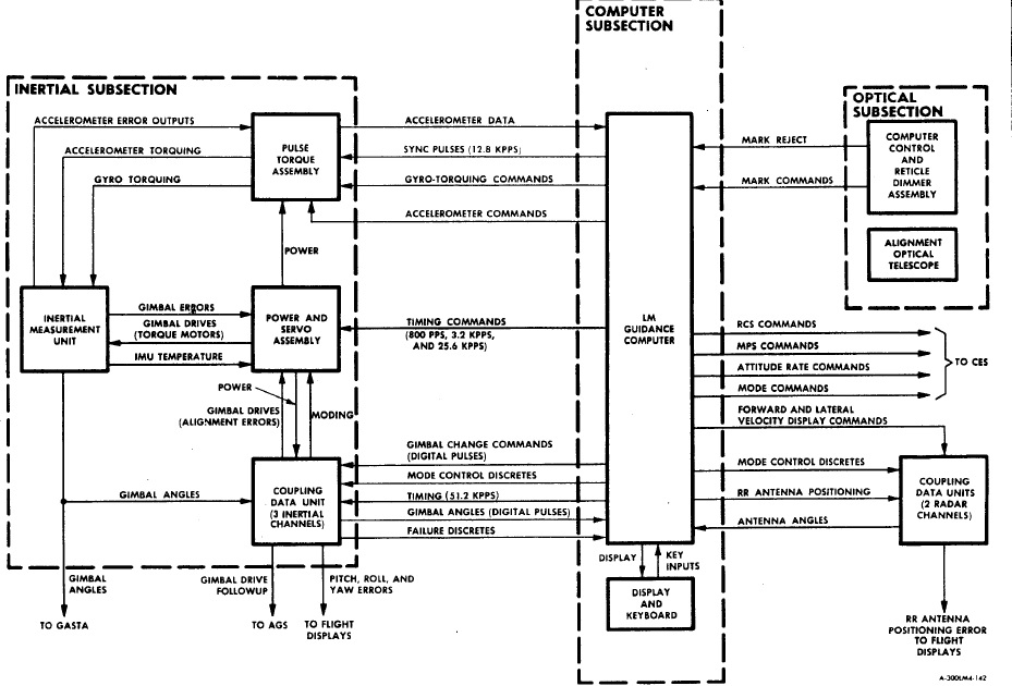 The AGC uses the fixed memory (the core rope memory) to make its programs run, and the erasable memory to store temporary data used by these programs, but, in order to communicate with the external environment (and in particular with the command of the main engine and the one of the RCS), it uses Input/Output ports, it can't do it directly with the memory. |
 In order to write on an I/O port, the AGC has a dedicated instruction called "WRITE"; the program puts into the accumulator the value to write on an I/O port, and then calls the instruction WRITE, giving as an argument the address of the I/O port on which the value stored in the acculumator must be written. It means that, in the program of the guidance routine, we should find several occurrences of this instruction to send commands to the main engine and the RCS. |
 And yet, in the whole program of the ascent routine, we can't find a single occurrence of this instruction, not even one! |
 The routine "THROTTLE" allows to control the thrust of the main engine. It is only called by the descent program, not by the ascent program. |
 But, in this routine, we cannot either find the instruction "WRITE" which would allow to send the calculated command to the main engine. It makes vain calculations which are used for nothing. |
 So, whatever the guidance routine does, it does not try to control either the main engine or the RCS, though it is supposed to do it. |
 Yet, if we examine the code of the guidance routine, it seems to make plenty of calculations, but these calculations do no follow a logical scheme, and they are not used to control the main engine or the RCS, their result is used for strictly nothing, it is a completely useless work! And it goes further than the work of this routine being useless, as we are going to see. |
 The program mainly uses macro-instructions which are described in the documentation of the interpreter. Some macro-instructions use two arguments (called X and Y), which follow on the two next lines, and others use a single argument (called X) which follows on the next line. |
 Here is an example of a macro-instruction with two arguments, the first one which is encountered in the ascent routine. The macro-instruction "BON" tests the switch specified by the first argument (FLRCS), and branches to the label specified by the second argument (ASCENT) is this switch is on. |
 And here is an example of a macro-instruction with a single argument. The macro-instruction "DSU" performs a double subtract of the value specified in the argument (YDOT) with the double accumulator (called MPAC) and puts the result into the double accumulator. |
 Now, on many lines of the program, we find two macro-instructions on the same line, which is not allowed, for each macro-instruction should be followed with one or two arguments, and this should have been rejected by the compiler. |
 The compiler is the software which analyzes the user's program, detects errors of syntax or of logic, signals them, and, when it finds no errors, generates the machine code which is understable by the computer. The compiler should have rejected most of the instructions of the ascent routine. |
 The program also uses incorrectly specified variables; the name of a variable cannot contain any of the operators '+', '-'; '*', or '/', for it creates a confusion with these operators. |
 This blued macro-instruction (STCALL) stores the double acculumator into TGO, and then makes a call to the label ASCTERM2. |
 It means that the program resumes from the label ASCTERM2. At this label, the instruction "EXIT" is used to get out ot the interpreter (called with "TC INTPRET", that we find at several occasions in the program), but we are not in the interpreter here, so this instruction should not be used here. This instruction is followed with the instruction "TCF ENDOFJOB" (go to ENDOFJOB) which terminates the routine, which means that there will be no return to the caller. |
 The macro-instruction "BPL" branches to the address specified by the argument which follows if the double accumulator (MPAC) is greater than or equal to 0; obviously the line which follows contains this argument, for RATES is a label we can find in the program; and the macro-instruction "SET" allows to set a switch which is specified on the next line; this switch is in fact specified on the line which follows the argument of "BPL" (FLPC). This way of crossing macro-instructions and their arguments is a complete fantasy, and is not a normal way of doing; it cannot be accepted by the compiler. |
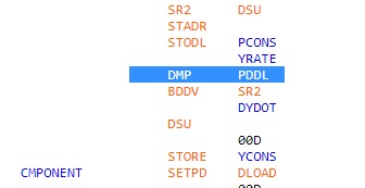 The macro-instructions "DMP" and "PPDL" both have an argument; they should not have been specified on the same line, and there is no argument after the line which contains them, since the next line contains a macro-instruction, not an argument. |
 The accumulator is calculated with the two instructions "CA FLAGWRD9" and "MASK FLRCSBIT"; the accumulator is then tested with the instruction "CCS A", and, if the result of this calculation is positive, the next instruction is executed, "TCF ASCTERM3", which one jumps to ASCTERM3. The two same instructions "CA FLAGWRD9" and "MASK FLRCSBIT" are executed again, giving exactly the same result as previously; so it is completely useless to make twice the same test, it is redundant; and, this time, the instruction following "CCS A" cannot be executed, as the result of the calculation cannot be positive, otherwise there would have been a branch to ASCTERM3 in the previous test. We obviously here have a waste of instructions, by uselessly repeating twice the same test. |
 When a subroutine is not in the same memory bank as the bank in which the current program is running, it cannot be directly called, but it has to be called with a special instruction "TC BANKCALL", followed with a declaration" CADR" having as an argument the name of the subroutine to call in this other memory bank. Here it is the subroutine "GODSPR" which is called, and this subroutine is in the program of the display, which is in another memory bank than the ascent routine, which explains the way it is called. |
 GODSPR returns to the address which follows the call, except if the verb/noun which is used corresponds to a flashing display; in this case, it returns to the address which is four lines after the call. |
 It means that, if GODSPR was called with a flashing verb/noun, the return would be made to the label "ASCTERM4"; from there, it would return to the label "ASCTERM1", executing again the same instructions, and we would have an infinite loop, which means that the guidance routine would never end. |
 In reality, the program GODSPR is called with the verb 06 and noun 63 (CAF V06N63), and, if we look in the documentation, we can see that this combination of verb/noun corresponds to a non flashing display. |
 So the return will correspond to a non flashing display, which means that in fact if will end with a branch to ENDOFJOB, terminating the guidance routine. It may mean that the program will not indefinitely loop (unlike it would have been the case with a flashing verb/noun), but it also means that there will never be a branch to ASCTERM4, and, consequently, that the instructions that I have barred with a cross will never be executed, and are thus an illogical waste of memory. |
 Further in the program, we see a call to the procedure "GOFLASH", which is also in the display program of the AGC, and which thus must also be called through BANKCALL. |
 In the comments associated to GOFLASH, we can see that the astronaut can end a flashing display in three different ways. - If he terminates it with the verb 34, the return will be made to the first instruction which follows the call to GOFLASH. - If he terminates it with the verb 33, the return will be made to the second instruction which follows the call to GOFLASH. - And, if he terminates it with the verb 32, the return will be made to the third instruction which follows the call to GOFLASH. |
 If the astronaut terminates the flashing display with the verb 32, the return will be made to the instruction "TCF -5" (go back 5 instructions before), which makes that the procedure GOFLASH will be called again. |
 We have another example a little farther, in which, if the astronaut terminates the flashing display with the verb 32, the program will loop back, and a new call to GOFLASH will be made again. It means that, if the astronaut systematically terminates the flashing display with the verb 32, he can make the guidance routine indefinitely loop. You might say that the astronaut would have to be stupid to block the guidance routine that way, and that he should terminate the flashing display with another verb, so that he would not block the guidance routine. |
 But, even so, he will take time to type the verb to terminate the flashing display, certainly more than 2 seconds, and a new guidance routine is started every two seconds, which means that the current guidance routine must take less than two seconds to run. In Apollo 11, the guidance routines have accumulated because of the fast pulses of the radar interface, delaying their execution... |
 ...and, here, it is going to be even worse, with the time that the astronaut needs to type the verb ending the flashing display, the delayed guidance routines are going to accumulate still faster, causing an overload of the computer. |
 And, when this overload of the computer occurs, the result is the famous 1202 alarm. |
 And, when the 1202 alarm occurs, the BAILOUT procedure is called to terminate the overload process, and, in another page, I have shown that this procedure was blocking the AGC, and preventing it from restarting. |
 But, anyway, why would the engineers have bothered to write a normal guidance program for a computer... |
 ...of which the memory was not even correctly working! |
 And, if the engineers have called its memory "LOL", it's not because it was meaning "Little Old Lady", as we have been led to believe, but because it was in fact meaning what it generally means, that is "Laughing Out Loud". |
 And, even if the AGC had really worked, and the guidance routine had really made sense, it still would not have helped, with a command interface for the RCS showing that each vertical command was activating two vertical thrusters directly opposed to each other on the same cluster... |
...Thus cancelling their mutual effects, which was preventing from making any rotation of pitch or roll. |
 The engineers really spared no effort to make sure that the only place that a lunar module would ever land on would be the fake moon set (in area 51), hauled with a crane. |

