
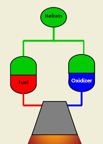
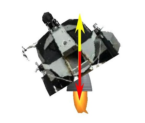
 This part describes the propulsion system of the lunar module. Link to the official NASA handbook of the lunar module containing the description of the propulsion system of the lunar module The lunar module's engine was working by mixing fuel with oxidizer. So there were two different tanks to feed the engine. |
 In fact, unlike the ascent engine, the descent engine can be swiveled, which allows to realign the main engine's thrust with the center of gravity of the lunar module, at the end of the descent, when the fuel tanks have emptied and there starts to be a disalignement of the center of mass with the thrust of the main engine, but it also means that the horizontal thrusters of the RCS are no more horizontal, and that firing them either makes the lunar module go up or down, which must be compensated by adjusting the main engine's thrust. |
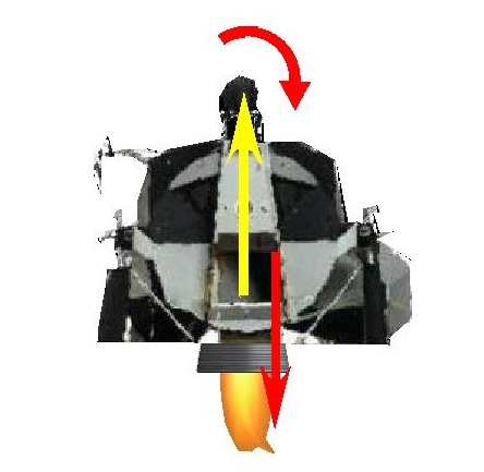 There is a confirmation of the disalignment of the center of gravity with the thrust of the main engine of the ascent module along the ascent in a document "Apollo progress report" written in the sixties by a NASA engineer, David Hoagland. David Hoagland says this: "The LM ascent powered flight autopilot obtains control torque only by means of the reaction jets. The engine is fixed; it cannot swivel. This control then operated very similarly to the free-fall coasting flight autopilots described above, but with the addition that the system estimates the torque arising from the offset of the main engine thrust from the center of gravity." Because the center of gravity is shifted from the axis of the ascent module as the tanks are emptying, the combined forces of the thrust and the lunar gravity create a torque which makes the ascent module turn clockwise. So that the ascent module keeps a steady direction, this torque needs to be corrected by applying a counter torque. |
 The only way of applying a counter torque is by firing the vertical lateral thrusters so that they produce torques which make the ascent module turn in the opposite direction. If the torque created by the lateral thrusters could be exactly equivalent to the misalignment torque, the lunar module could keep going straight. But the lateral thrusters could not be throttled, they were working in "all or nothing", and consequently it was not possible to adjust their thrust so that they would create a torque exactly equivalent to the misalignment torque. The consequence is that they could not be permanently fired, but periodically instead; and as they could not be activated at a sufficient frequency (the guidance period was 2 seconds), the result is that it was not possible to avoid a consistent swaying move. |
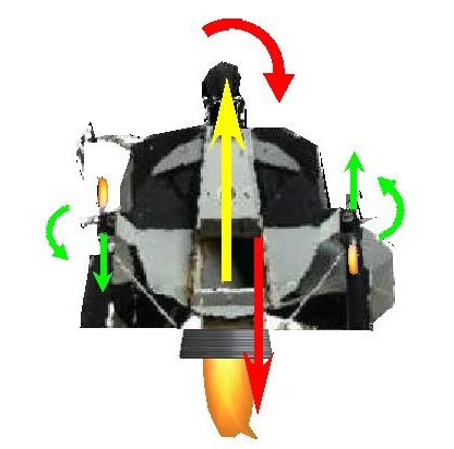
 This animation explains what was happening: The misalignment torque was making the LM turn clockwise and go right; then the lateral thrusters were fired, and were making the LM turn counterclockwise, and go left; then the lateral thrusters were shut off (otherwise they would go on making the LM turn counterclockwise and go left), and the misalignment torque was making the LM turn clockwise and go right again, and so on. The more the misalignment torque was strong, and the more the amplitude of the oscillating move was consistent, for the frequency of command of the lateral thrusters could not be increased to counter the misalignment torque faster. |
 This is absolutely not a supposition I am making, this is confirmed in the documentation by the NASA engineers. Even Clavius is talking about it on his site, and saying this: " As the off-axis thrust caused the ascent stage to rotate, the RCS jets fired to counter the rotation and return it to the correct attitude. This is why the films of the LM ascent seem to show a periodic sway or oscillation: the RCS "fought" the off-axis ascent engine." |
 The fact that the tank of the oxidizer is placed closer to the ascent engine is explained by the fact that the oxidizer has a greater density than the one of the one of the fuel (1.5 times greater). If they were placed at the same distance, the difference of density of the propellants would make the LM turn on the side of the oxidizer tank. At the beginning of the ascent, when the tanks are full, their contents are heavier than the containers, so the misalignment torque is limited. But, as the tanks are emptying, the difference between the contents and the containers decreases, and consequently the center of mass of the LM shifts toward the fuel tank, with the consequence that the misalignment torque increases; as the lateral jets of the RCS cannot increase their frequency of correction of the misalignment torque, the consequence is that the amplitude of the oscillation of the LM progressively increases. (The purpose of this animation is to make understand what happens and not to represent the exact reality). |
 Yet, it was absolutely not the interest of the LM to waste the fuel of its RCS, for it would need it at the crucial final phase when it makes its flipover maneuver to dock to the LM. |
Was there a way to avoid using the RCS to correct the attitude of the LM? |
 Absolutely there was, and there even were several possible ways. A first obvious way would have been to move a weight inside the lunar module to allow to shift the center of mass; the interest of this is that the ascent engine would remain in the axis of the lunar module. |
 Another way would be to allow the engine to be swiveled, which would also allow to move the center of gravity on the line of the thrust; but the disadvantage of this is that the ascent engine would not be in the axis of the lunar module any more. |
 Both ways would allow to avoid using the RCS to control the attitude of the LM which is only necessary because the center of gravity is not aligned with the thrust. Not only it would give a more regular trajectory to the LM, but it would simplify the guidance, and, most important, it would allow to save the fuel of the RCS so vital for the final phase of the approach. The NASA engineers made it illogical on purpose. |
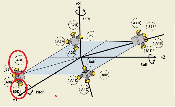
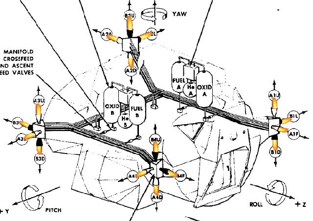
 The engines of the RCS are placed at the four corners of the lunar module. |
 Each RCS module has four engines, two horizontal, and two vertical, which allow to turn the lunar module in all directions (by combining all the engines of the RCS). |
 Each engine is activated by an individual command. A logic allows to individually activate the engines of the RCS. |
 The engines of the RCS which must be fired to apply the desired torque countering the misalignment torque in the ascent are those I have circled on this schema and are designated as A3U, B4U, A2D, and B1D, according to the terminology of the RCS. They must all be fired in the same time in order to avoid a disbalance. |
 This schema shows the interconnection of the valves of the RCS. When the RCS must be fed in fuel, the two fuel valves have to be open. When the RCS must be fed in oxidizer, the two valves of the oxidizer must be open. But, if any of the valves refuses to open, the RCS cannot be be fed either in fuel or in oxidizer, and then cannot work, because it needs both the fuel and the oxidizer to work. |
 So, why not have used this simpler schema? The RCS will not work only if one of 2 valves does not work, and there is less chance that one in 2 valves does not work than 1 in 4 valves. Now, with this schema, the RCS will not work correctly if a valve refuses either to open or to close; in the previous schema, it is only if a valve refuses to open that it won't work; if it refuses to close, the other valve which closes will allow to block the fuel of the oxidizer. |
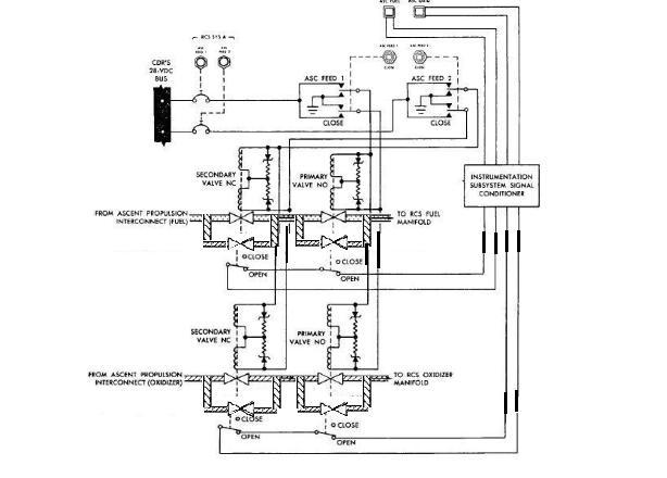 So, if the system must really be guarded against the failure of a valve, it is rather this system which should be used, with a duplication of the valves: If a valve refuses to open, the other valve which opens will still allow to let the fuel or oxidizer through, and, if a valve refuses to close, the valves of the other pair, which will be both closed, will allow to block the fuel or oxidizer. There is a full security about the failure of a single valve, either refusing to open or to close. |
 This is the schema of the propellant measuring device. It uses analog computers to work, that is electronic interfaces using operational amplifiers. |
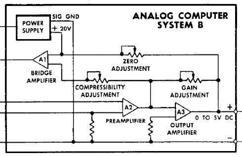 This is the schema of an analog computer of the propellant measuring device. |
 I see major faults in this schema. The connections I have barred with red crosses should not exist. And the adjustable resistors I have circled should not exist either. Only the gain adjustment should exist. |
 This is what the analog computer should have looked like to be normal, without the abnormal connections, and unnecessary adjustable resistors. |
 This is the schema of the thrust chamber assembly, with the individual commands for each engine of the RCS. |
 The commands of the RCS are elaborated from the LM's attitude angles and the translation vector. |
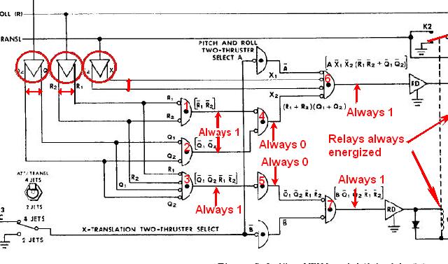
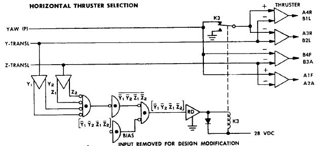 This is the the schema of the horizontal thruster selection which elaborates the commands for the horizontal engines of the RCS. |
 The devices I have framed are electromechanical relays; an electromechanical relay is composed with a coil I have circled in green, and a switch which is changed state by energizing the coil, and that I have circled in orange. |
 Here is how the electromechanical relay works: - When the coil is not energized, the central point of the switch is connected to the upper contact. - When the coil is energized, it attracts the switch down, and the central point of the switch becomes connected to the lower contact instead. |
 If the lower contact of the electromechanical relay is connected to the ground, the effect is that the output of the electromechanical relay is connected to the ground when its coil is energized. |
 The circuit I have circled in red is an OP amp with two outputs; these outputs are complementary to each other: When one is 1, the other one is 0, and vice versa. The circuit I have circled in orange is an OR gate with inverted inputs. |
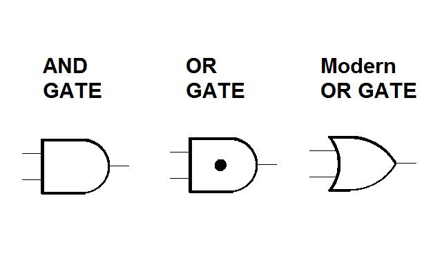 In the symbology of Apollo, the AND gates and the OR gates are represented with the same symbol, but with a black point inside the OR gate to differentiate it from the AND gate. |
 An OR gate is a circuit which has several inputs (at least two), and which outputs a 1 if at least one of the inputs is 1, and 0 only if all the inputs are 0. |
 When there is a little circle before the inputs, this little circle means that the inputs are inverted before being applied to the OR gate (i.e. a 0 becomes 1 and vice versa). The OR gate then outputs a 0 if all the inputs are 1, and a 1 otherwise (i.e. if at least one input is 0). When there is only one input to that circuit, the output of the circuit is the inverted input. |
 Knowing this, we now can analyze this circuitry. The circuits I have circled produce two outputs from the command inputs (I indicate with double arrows) which are complementary, which means that, when one is positive, the other one is negative and vice versa. These outputs are inverted before being ored; as the outputs are complementary, so are the inverted outputs, which means that, when one is 1, the other one is 0, and vice versa; oring inputs means that the resulting output is 1 is one if one at least of the inputs is 1; here the little circles indicate that the inputs are inverted before being ored; and the inverted complementary inputs are also complementary, which means that one at least of the inverted inputs is 1, and consequently the output of the OR circuit 1 is always 1; this output is inverted by the next circuit, which means that the output of the circuit 2 is always 0; this output is inverted before being ored with another output, which means that the output of the circuit 3 is always 1; and the output of the circuit 3 goes into an Op Amp which will always energize the electromechanical relay that it is connected to, as the output of the circuit 3 is always 1. |
 As the electromechanical relay is always energized, no matter what, the switch that it is connected to will always be on the down position, that is connected to the ground. That means that they could as well have connected the two inputs which are connected to the switch directly to the ground, the result would have been the same. Now, the inputs of A4R/B1L and A3R/B2L are both Y-TRANSL and the ground, which means that A4R/B1L and A3R/B2L could have been connected directly to the same command. Likewise, the inputs of B4F/B3A and A1F/A2A are both the Yaw and Z-TRANSL, which means that B4F/B3A and A1F/A2A could also have been connected to the same command. And as the K3 relay is always energized, and thus connected to the ground, it means that the yaw command does not go into 4 horizontal thrusters; yet it should be able to go into all the horizontal thrusters, for all allow to turn the lunar module around the vertical axis (yaw) in both directions. Now, the main point is that it makes no sense to compare rotation commands with translation commands to activate the lateral thrusters; indeed, the lunar module can be either rotated or translated, but not both in the same time; moreover there is no notion of the sign of commands; indeed, according to the direction that the lunar module is turned or translated, it is not the same thrusters which are used. In fact, there should have been two inputs per rotation or translation command, one for each direction (for instance, Yaw+ to make the lunar module turn counterclockwise - the positive trigonometrical direction- and Yaw- to make the lunar module turn clockwise - the negative triginometrical direction). And only one horizontal command would have been 1 at a time, and all the other ones 0. The commands of the lateral thrusters would then have been a logical combination of the couples of horizontal commands. |
 For instance: - the lateral thruster A1F would have been activated if either Yaw+ or Z- is 1, and not activated in all other cases. - the lateral thruster B1L would have been activated if either Yaw- or Y+ is 1, and not activated in all other cases. - the lateral thruster B4F would have been activated if either Yaw- or Z- is 1, and not activated in all other cases. - the lateral thruster A2A would have been activated if either Yaw- or Z+ is 1, and not activated in all other cases. Each thruster is activated either by a rotation command or a translation command. |
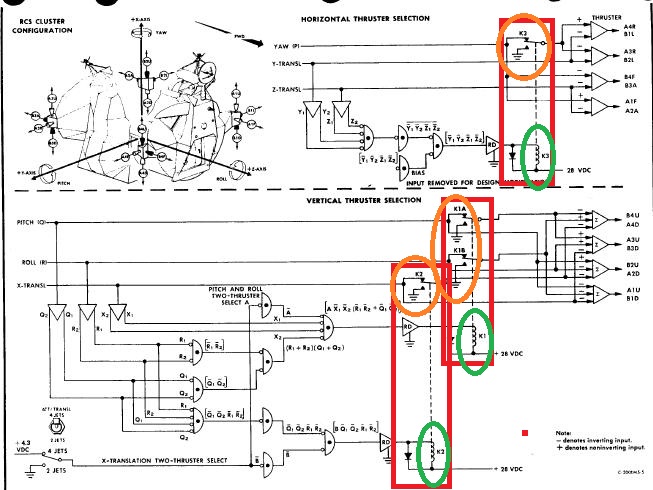
 This is the the schema of the vertical thruster selection which elaborates the commands for the vertical engines of the RCS. |
 The circuits I have circled produce two outputs from the command inputs (I indicate with double arrows) which are complementary, which means that, when one is positive, the other one is negative and vice versa. For the same reason as previously explained, the outputs of the circuits 1,2, and 3 are always 1. The circult 4 receives two inputs which are always 1, but are inverted before being ored, which means that two 0 are ored, which gives a 0; the output of the circuit 4 is thus always 0. For the same reason, the output of the circuit 5 is also always 0. The output of the circuit 4 is inverted before being ored with other inputs; the inverted 0 becomes a 1 again, and the output of the circuit 6 is thus always 1; if feeds an OP amp which will always energize the electromechanical relay it is connected to. For the same reason, the fact that the output of the circuit 5 is always 0 has for consequence that the output of the circuit 7 that it is connected to will always be 1; if feeds an OP amp which will always energize the electromechanical relay that it is connected to. |
 As the electromechanical relays are always energized, the switches will always be on the down position, that is grounded, which means that all the inputs which are connected to these switches could have directly been connected to the ground, which means that these inputs are useless, and two inputs would have been enough for the Op Amps. Now, the first Op Amp, the one which is circled, has all its inputs to 0 (because of all relays being forced to the ground); that means that the vertical thrusters B4U and A4D it commands will never be activated. The main point is the same as for the command of the horizontal thrusters: Instead of incoherently comparing the vertical commands, there should have been two inputs for each vertical command, one for each direction, and only one input set to 1 at a time, and the commands of the vertical thrusters would have been a logical combination of the couples of vertical commands (like I showed on the horizontal commands). Once again, we here have a total fantasy. |
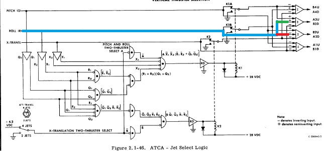 Now we can see that the Roll command (which is normally the command which allows to apply the counter torque) is inputted on the + input of the command of the pair of engines A3U and B3D, and on the - input of the command of the pair of engines B2U and A2D; it means that it will activate the engines A3U and B3D when positive, and the engines B2U and A2D when negative, but never the four of them in the same time. |
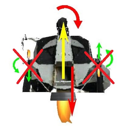
 Now, it's where it becomes really tasty: The engines A3U and B3D, which are activated in case of positive roll, are two vertical engines directly opposed to each other; it means that they are going to mutually cancel their respective effects, and so the consequence is that the positive roll command...does NOTHING! |
 And the engines B2U and A2D, which are activated in case of negative roll, are two vertical engines which are also directly opposed to each other; it means that they are also going to mutually cancel their respective effects, and so the consequence is that the negative roll...also does NOTHING! |
 And we can see that the Pitch command is inputted on the + input of the command of the pair of engines B2U and A2D, and on the - input of the command of the pair of engines A1U and B1D; it means that is will activate the engines B2U and A2D when positive, and the engines A1U and B1D when negative. |
 And once again we find the same joke as for the roll command; The engines B2U and A2D, which are activated in case of positive pitch, are two vertical engines directly opposed to each other; it means that they are going to mutually cancel their respective effects, and so the consequence is that the positive pitch command...does NOTHING. |
 And the engines A1U and B1D, which are activated in case of negative pitch, are two vertical engines which are also directly opposed to each other; it means that they are also going to mutually cancel their respective effects, and so the consequence is that the negative pitch...also does NOTHING. |
 How can the RCS work when each command of the lateral vertical thrusters activates two vertical thrusters directly opposed to each other on the same cluster, thus cancelling their mutual effects. The lunar module was simply unable to control its attitude, which was making both the powered ascent and the powered descent impossible (and also impossible to compensate the misalignment torque with the lateral thrusters). |
 Here the NASA engineers have pushed the joke very far. But they have even pushed the joke further as we are going to see. |
 Now, an Apollo believer has thought to save the situation by showing me this logic table, in which the commands activate thrusters on opposite clusters. This table contradicts the schema we have seen, and, even if it seems more coherent than the schema, it still has a big problem: Each command acts both on the pitch and the roll. With this table, it is impossible to pitch without rolling and vice versa. In fact pitching without rolling, or rolling without pitching, cannot be done with two thrusters only. Four thrusters are required to make it, and the following schemas are going to show how. |
 This schema shows how the lunar module can be pitched up, by firing the thrusters A4D, B1D, A3U, and B2U. |
 This schema shows how the the lunar module can be pitched down by firing the thrusters B4U, A1U, A2D, and B3D. |
 This schema shows how the lunar module can be rolled left by firing the thrusters A4D, B3D, A1U, and B2U. |
 This schema shows how the lunar module can be rolled right by firing the thrusters B4U, A3U, B1D, and A2D. |
 ...Anyway, even with a correct interface for the jet selection logic, this clown of AGC would still have been unable to control it correctly! |
 The normal way for the AGC to ccontrol the RCS is to acquire the attitude angles and update the LM's position from accelerometers, compare the measured angles and position with the ones which are desired by the guidance, and compute commands from the differences between measured and desired data that it sends to the RCS. |
 The AGC updates angles (and accelerations) by incrementing or decrementing counters according to the direction of angle's variation (with "hidden" instructions, which is a heresy, as I have already pointed out, for incrementing or decrementing these counters should be made by hardware); the guidance computes angles and position according to the trajectory which is to be followed; a measured angle is compared with the corresponding desired angle; the difference is compared with a threshold; if the difference is over the threshold, the thrusters which make this angle increase are activated if the difference is positive (i.e. desired angle greater than measured angle), and conversely the thrusters which make this angle decrease are activated if the difference is negative; if the difference is under the threshold, no thruster making this angle change is activated. |
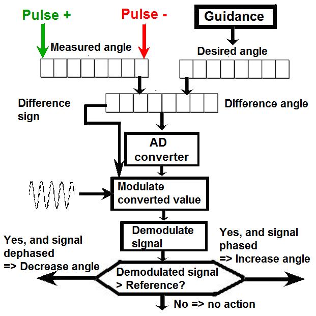 Now, what they do is a little different. They compute the difference between these two values of the angle in a counter, and they convert this counter into an analog value with a digital to analog converter; the converted analog value modulates a high frequency signal, and the phase of this signal is set according to the sign of the difference. Then this modulated signal is demodulated, and the demodulated signal is compared with a reference; if the demodulated signal is over the reference, the thrusters which make this angle increase are activated if the modulated signal is phased, and conversely the thrusters which make this angle decrease are activated if the modulated signal is dephased; if the demodulated signal is under the reference, no thruster making this angle change is activated. This is uselessly complicated, it is much simpler to proceed like I previously showed, by just comparing the difference counter with a binary threshold, and activate thrusters if the difference is over this threshold according to the sign of the difference. Converting the difference of angles to analog would only have made sense if the thrust of the lateral thrusters could have been adjusted; in that case the converted analog value could have been used to adjust the thrust of the lateral thrusters. But, as their thrust cannot be adjusted, and they work in "all nothing", i.e. they can either be fully activated of not at all, but not partially, the conversion of the angle difference into an analog value is an useless complication. It cannot be said that this way of doing is completely impossible, but it is an useless complication, and engineers intending to make a serious project would never make useless complications. |
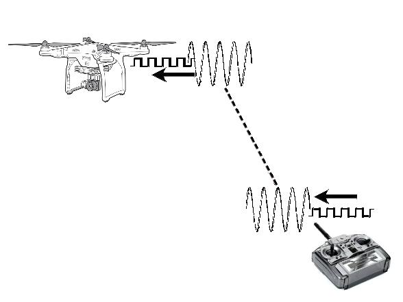 But this is completely absurd! When commands are to be transmitted from a controller to a drone, as there is no wire connection between the controller and the drone, the only way to transmit the commands of the controller to the drone is to modulate a high frequency carrier with the commands, so that these commands can travel through air up to the drone; in the electronic circuitry of the drone, the high frequency carrier is demodulated, and the controller's commands are extracted from it and applied to the drone. |
 But in the case of the RCS control, the commands are directly sent through wires, and not through air, and so this is a completely useless complication, uselessly complicating the circuitry and wasting power. |
In other words, this completely useless complication is nothing but a new joke from the NASA engineers for an interface which anyway does not work and cannot make the RCS control the attitude of the lunar module. |
 So now we have a misalignment torque which comes from the shift of the center if gravity which cannot be corrected by swiveling the ascent engine since it is fixed; this misalignement torque cannot be countered by the lateral engines of the RCS since we have seen it can't work. |
 The consequence is that the lunar module is going to turn like a girouette, indefinitely, without this rotation having a mean of being countered. |
 The result is to be expected: The lunar module is going to crash on the lunar ground shortly after having lifted off. |
 Because, as the guidance task was unable to work regularly, very often the commands sent to the engines were not sent in time, which was causing unwanted dangerous oscillations! |
 Since the engines are so important, and so vital for the safety of the lunar module, since their failure would fatally mean death for the astronauts, it is obvious that the NASA should have to be absolutely sure that they are in perfect working order before sending the LM to the moon, without the least doubt, even the smallest one. Yet, on Apollo 10, during several of the lunar orbits, a critical fuel-cell temperature started to oscillate significantly, as shown on this figure. |
 An investigation led in a laboratory revealed that small, isolated disturbances in fuel-cell temperature were often present, as shown on this figure. |
This investigation demonstrated that small, isolated disturbances could trigger an instability if the power loading ran sufficiently high and the temperature sufficiently low. From this this information, they devised procedures to eliminate the oscillations, should they occur. It is absolutely obvious that, this showing that the engine had a potential problem, even if they thought to have settled the problem, they should have sent another mission to check if the problem was really solved, and study in depth to get sure that the problem was no more occurring, since the engines are so vital for the safety of the mission, and that a failure of them is not allowed. |
 Not at all, they directly sent the next mission, Apollo 11, to the moon, with this "sword of Damocles" hanging over the safety of the ship; they left it to "chance". |
 Now, let's see what is done in the descent program. The first program of the powered descent had the responsibility of putting the main engine at full thrust, for the initial phase of the powered descent, the braking phase, was consisting in consistently decreasing the important orbital speed, so to arrive near the lunar surface with a moderate speed. |
 This program had been baptised "Burn Baby Burn" by the team of the MIT, which had been inspired by a musical group. |
 This program is included in 21 pages of the listing of the AGC. Does it need that much code to make its work? Link to the program "Burn Baby Burn" |
 In order to communicate with the external environment (with the LGC in particular), the AGC was using input/output ports. |
 The LGC could automatically set the engine on or off (what the astronauts could also manually do with the engine start/stop button) with ENGINE ON and ENGINE OFF commands. |
 The AGC had an access to the commands ENGINE ON and ENGINE OFF through two bits in the channel 11. Writing a 1 in the bit 13 of this channel was allowing to send an ENGINE ON command, that is to set the engine on, and writing a 1 in the bit 14 of this channel was allowing to send an ENGINE OFF command, that it to set the engine off. |
 In order to write on an output channel the AGC was using the instruction "WRITE". |
 This instruction is used only once in the program of Burn Baby Burn, with a channel identified as "DSALMOUT". |
 This mnemonic corresponds to the value 11. It means that the program is writing in the channel 11, that is the channel containing the ENGINE ON and the ENGINE OFF commands. |
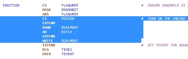 Now, let's see what is done in the program burn baby burn. |
 The instruction "CS PRIO30" puts the complement of PRIO30 into the accumulator. |
 PRIO30 is defined as having the bits 13 and 14 set to 1, and all the other bits set to 0. |
So, after having been complemented (i.e. the bits inverted), the accumulator now has its bits 13 and 14 set to 0, and all the other bits set to 1. |
 The instruction "RAND DSALMOUT" reads the channel 30, and makes an AND of the accumulator with the contents of channel 11. As the accumulator was having all its bits set to 1 save the bits 13 and 14, the accumulator now contains all the bits of channel 11, save the bits 13 and 14 which are set to 0. |
 The instruction "AD BIT13" adds the value defined by BIT13 to the accumulator; this value has the bit 13 set to 1 and all the other bits set to 0. It means that the bit 13 of the accumulator is set to 1, while the bit 14 remains set to 0. |
The instruction "WRITE DSALMOUT" writes the contents of the accumulator into channel 11. The result is that the bit 13 of channel 11 is set to 1, while its bit 14 remains set to 0. |
So the program burn baby burn effectively starts the engine. But this program must not only start the engine, it must also set its thrust at maximum for the initial braking phase, and it fails to do it, it does not adjust the thrust of the main engine. |
 The programs of the powered descent call a routine "THROTTLE", which is supposed to adjust the thrust of the main engine; so, if the AGC can control the thrust of the main engine, we should find in it WRITE instructions to send commands to the control of the thrust. But we can't find any, so this program does not control the thrust of the main engine. |
 Now, how was the thrust adjusted? The way that it was adjusted is described in the technical manual of the lunar module. The INCREASE THROTTLE and DECREASE THROTTLE commands were inputs to a counter; the INCREASE THROTTLE command was allowing to increment the counter, and the DECREASE THROTTLE command was allowing to decrement the counter. The output of the counter was allowing to control the thrust of the engine when it was the LGC which had the control of the thrust (that is when the Engine control mode was on AUTO). |
 Sending a pulse on the INCREASE THROTTLE command was allowing to increment the counter, and thus to increase the thrust of the engine. The documentation says that each pulse on INCREASE THROTTLE was increasing the thrust by 2.7 pounds. |
 Conversely, sending a pulse on the DECREASE THROTTLE command was allowing to decrement the counter, and thus to decrease the thrust of the engine. The documentation says that each pulse on DECREASE THROTTLE was decreasing the thrust by 2.7 pounds. |
So increasing the thrust was done by sending trains of pulses on the INCREASE THROTTLE command, while decreasing the thrust was done by sending trains of pulses on the DECREASE THROTTLE command. The maximum thrust of the main descent engine was 9900 pounds, and the minimum thrust was 1280 pounds. So, if each pulse on the INCREASE THROTTLE and the DECREASE THROTTLE commands was making a variation of 2.7 pounds of the thrust, it means that the thrust could be adjusted by (9900-1280)/2.7=3192 steps. This could be made with a command of 12 bits (12 bits represent a value of 4096). It means that there should be an output channel of the AGC on which 12 bits are reserved for the control of the thrust. |
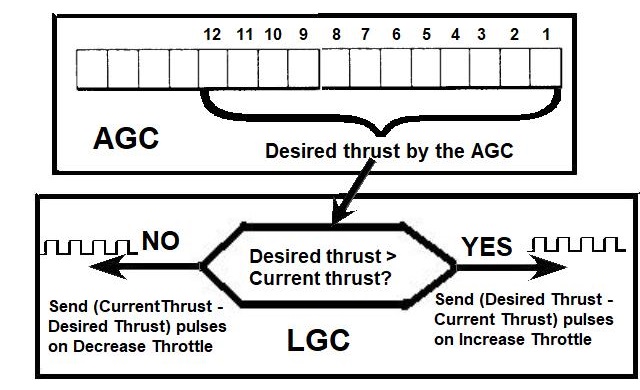 It would then work this way. When the AGC wants to set a desired level for the thrust, it would write the corresponding level on 12 consecutive bits of a decidated channel. The LGC would then use this desired thrust to compare it with the current thrust: - If the desired thrust is greater than the current thrust, the LGC would send (Desired thrust-Current thrust) pulses on the command INCREASE THROTTLE to increase the counter controlling the thrust by this value. - If the desired thrust is smaller than the current thrust, the LGC would send (Current thrust - Desired thrust) pulses on the command DECREASE THROTTLE to decrease the counter controlling the thrust by this value. This way the current thrust would be maintained equal to the desired thrust of the AGC. |
But, after having attentively examined all the channels used by the AGC, I could see that there was no channel which was allowing the AGC to control the thrust of the main engine. |
 Yet, the 12 bits preceding the bits of the ENGINE ON (bit 13) and the ENGINE OFF (bit 14) could perfectly have been used by the AGC to specify the desired level of thrust. Instead of that, these bits are only used for light indicators. The powered descent could perfectly be done without these light indicators, but it could not be done if the AGC could not control the thrust of the main engine (the thrust is set at maximum at the beginning of the powered descent, and decreased after the braking phase; and, when the lunar module is moving over the lunar surface in order to find a spot to land on, the thrust is continually adjusted to compensate the lunar attraction, as the weight of the lunar module decreases). Moreover, there are are plenty of spare bits in other channels which could have been used for these light indicators. |
 There are bits in a channel (channel 12) to act on the gimbaling system of the descent engine (to change its orientation), but none to act on Throttle+ and Throttle-. Anyway, if there had been bits to act on Throttle+ and Throttle-, they would have needed to be triggered a consequent number of times to change the throttle, as they change the throttle by a very small amount at each time. |
 The conclusion is that the thrust of the main engine could not be adjusted by the AGC, which was making the powered descent impossible. |
 And that's not all. As the level of the propellants gets lower in the tanks, as the engine was burns them, their weight decreases, while the weight of the structure does not change, which means that the global center of mass of the lunar module gradually shifts, especially from Apollo 15, in which the lunar rover was stowed in a compartment of the lunar module. If the engine's thrust was remaining oriented along the vertical axis of the lunar module, that would cause a growing misalignment torque. |
 But, unlike the ascent engine, the descent engine was gimbaled, which was allowing to reorient the thrust toward the new center of mass. |
 The part of the descent control assembly which allows to control the gimbaling system has been contoured in red. |
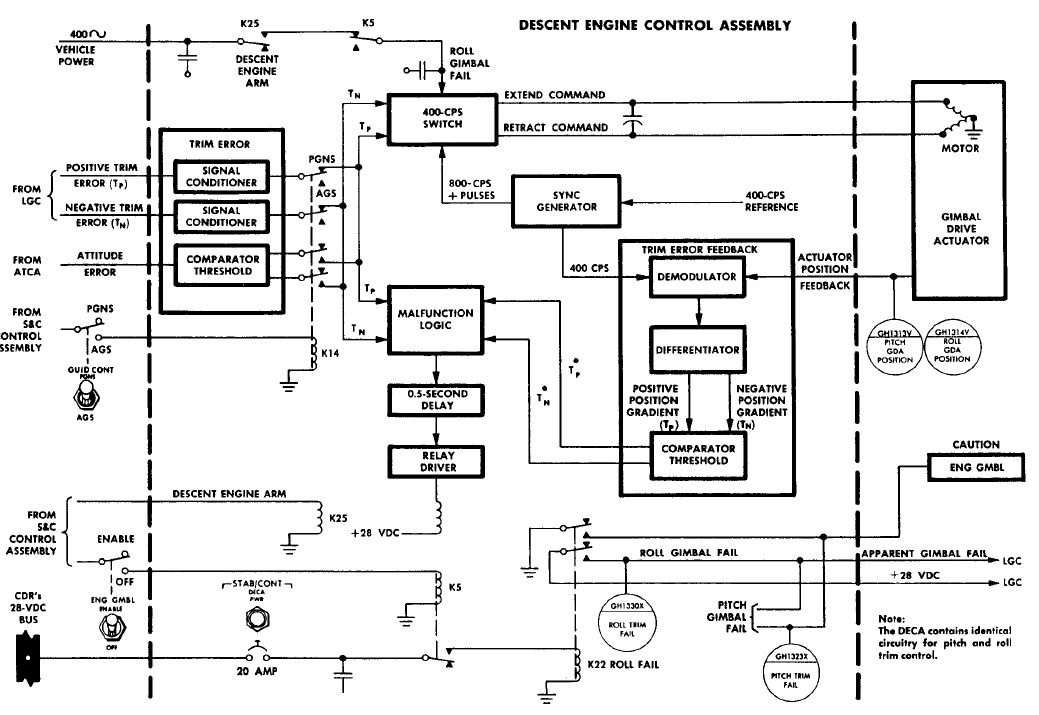 This is the diagram of the trim control of the roll angle of the gimbaling system. The diagram of the trim control of the pitch angle is similar. The roll angle of the gimbaling system increases as long as the positive trim input is activated. Likewise,the roll angle of the gimbaling system decreases as long as the negative trim input is activated. But, in order to correctly adjust the roll angle of the gimbaling system, there should be a feedback to the AGC, which should be able to read the current roll angle of the gimbaling system, otherwise the AGC will not be able of adjusting a determined roll angle. |
But, among all the communication channels between the AGC and the LGC, there is no channel input which allows the AGC to read the roll and pitch angles of the gimbaling system, and, without the knowledge of these angles, it is impossible for the AGC to precisely adjust these angles. |
 There are commands in an output channel (the channel 12) which allow the AGC to control the gimbaling system in the two directions (pitch and roll). |
 But the program P66 does not try to command the gimbaling system either, for it never tries to write into the channel (12) which contains the commands which act on the gimbaling system. Anyway, as the AGC cannot read the roll and pitch angles of the gimbaling system, it would be unable to adjust these angles, even if it was trying to write in the commands acting on the gimbaling system. |
 Apart from this major problem, there are other problems, with illegal instructions like the ones we have seen in the ascent program, that is two macro-instructions defined in the same line; these instructions should not even have been accepted by the compiler. |
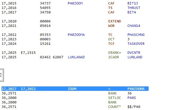 This affectation, making an equivalence between two addresses, is impossible. An address has a unique value which is determined by the compiler, and it cannot be changed. The label "ZOOM" is associated to the address 2027, while the label P40ZOOMA is associated to the address 2022; saying that ZOOM is equal to P40ZOOMA would be equivalent to saying that 2027 is equal to 2022, which is of course absurd. |
 It is possible to dynamically manipulate addresses by using pointers. A pointer is not an address, it is a data, but the difference with an ordinary data is that, instead of containing a simple value, it can contain an address. |
 Pointers are very practical to accede to structures. When the address of a structure is put into a pointer, it is possible to accede to all the members of this structure indirectly through this pointer. Pointers are much used in C, and, in C++, they allow to use classes. |
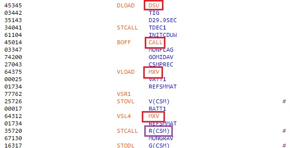
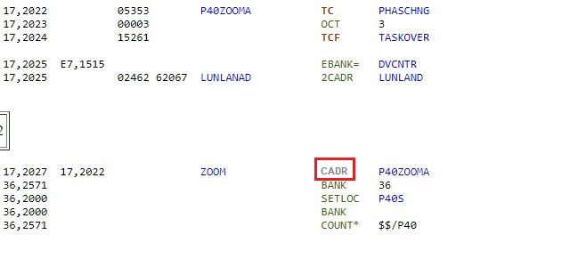 If the affectation which is shown is illegal, it could be defined by using the declaration of address "CADR". CADR defines a a data which contains an address. The address of this data would be "ZOOM", and its contents would be "P40ZOOMA". This declaration is used to make calls to routines which are on another memory bank than the current memory bank, by making a call to "BANKCALL". BANKCALL looks for the contents of the address which follows its call, and finds in it the address of the routine to call. |
 And now a final clue in this program. In the routine "COMFAIL", the couple of instructions "TC BANKCALL","CADR STCLOK1" makes a call to STCLOK1. |
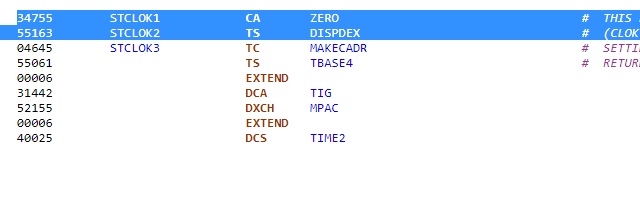 In STCLOK1, the instruction "CA ZERO" loads 0 into the accumulator, and the next instruction, "TS DISPDEX", puts the accumulator into the variable DISPDEX; it means that DISPDEX now contains zero. |
 Further, the couple of instructions "TC TWIDDLE", "ADRES CLOKTASK" starts a task called "CLOKTASK". The program continues in sequence, and gets itself into CLOKTASK. |
 And now the surprise lies in CLOKTASK. |
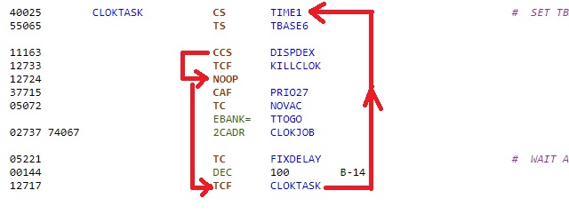 In CLOKTASK, the instruction "CCS DISPDEX" tests DISPDEX, executes the first next instruction if DISPDEX is positive, and the second next instruction if DISPDEX is null. But we have seen that DISPDEX has been set to zero at STCLOK1, so it is the second next instruction which is executed, the instruction which would have allowed to get out of CLOKTASK is skipped. The program continues in sequence, till an instruction "TCF CLOKTASK" which loops back to the beginning of CLOKTASK. And bingo, the whole sequence indefinitely repeats itself. |
 So we here have a beautiful infinite loop, and no program has ever managed to get out of an infinite loop. |
 Just before the touchdown, as the lunar module was moving over the lunar surface in order to find a safe spot to land on, the crew was using the semi-automatic program P66. This program was only controlling the thrust of the main engine, so to compensate the lunar attraction, while the crew was controlling the RCS (lateral thrusters) to move over the lunar surface. This program was also taking into account orders of the crew to move down or up the lunar module, so that the crew could choose at what altitude the lunar module had to move over the lunar surface. As we have seen that the AGC could send a command to the LGC to control the thrust, we already know that there will be a problem in the program P66, since it cannot physically apply what it has computed. But we can check if it computes something which makes sense, so that, if it could have sent the calculated command to the LGC, it would have worked. For that purpose, I have to explain how the program P66 should have worked. |
 In order to remain over the lunar surface, at a constant altitude, the engine of the lunar module has to perfectly compensate the lunar attraction. The lunar attraction exerts on the lunar module a downward force which is equal to the lunar gravitational constant (that I'll call "g") multiplied by the current mass of the lunar module (that I'll call "M"), expressed in kilograms, this force being expressed in Newtons. So the main engine must produce a force (that I'll call "F") which is equal to this downward force, so that the lunar module does not fall toward the moon. |
 If the main engine produces a force which is less than the lunar attraction, the lunar module is going to fall toward the lunar surface with an acceleration which is equal to g-F/M. |
 Likewise, if the main engine produces a force which is more than the lunar attraction, the lunar module is going to move up with an acceleration which is equal to F/M-g. |
 When the crew desires to descend, it uses a "DESCENT-" command which means that the force produced by the main engine is momentarily less than the force which is necessary to compensate the lunar attraction; the result is that the lunar module starts descending; and when the lunar module has reached the desired alltitude, the crew uses a "DESCENT+" command, which increases the force produced by the engine, and so stops the descent of the lunar module; thereafter, the thrust of the main engine is maintained equal to the lunar attraction, so that the lunar module remains at that altitude. |
 Likewise, when the crew desires to ascend, it uses the "DESCEND+" command, which one momentarily increases the force produced by the main engine, so that the lunar module starts to ascend; when the lunar module has reached the desired altitude, the crew uses the "DESCENT-" command, which decreases the force produced by the main engine, and so stops the ascent of the lunar module; thereafter, the thrust of the main engine is maintained equal to the lunar attraction, so that the lunar module remains at that altitude. |
So, what does the program P66 needs to do its work? First it needs to know the current mass of the lunar module. It could calculate it as the sum of the dry mass and the mass of the remaining propellants. |
But the AGC does not have the information of the remaining propellants on its channels, so it cannot update the mass this way. |
But the AGC can also update the current mass in another way, by using the information of the acceleration (provided by the vertical accelerometer). Indeed, when the current thrust does not compensate the lunar attraction, it generates an acceleration (that I'll call "a") which is equal to: a=g-F/M, "a" being positive when oriented downward. Consequently, the mass can be calculated with the formula: M=F/(g-a), which allows to update the current mass of the lunar module by the knowledge of both the current thrust applied by the main engine and the current measured acceleration. |
 And the AGC has a way of knowing the current acceleration, for the IMU sends to it pulses that the AGC must count to update it, with special "hidden" instructions ("hidden" means that they are not used by the programmer, and that they execute independently of the current program), called "PINC" and "MINC", the same instructions which caused an overload of the computer in the descent of Apollo 11, because of fast radar pulses, and which generated a 1202 alarm. |
 And, concerning the commands "DESCENT+" and "DESCENT-" used by the crew to move the lunar module up or down respectively, they can by found on the bits 6 and 7 respectively of channel 16. |
 So, we can now examine the work which is done by the program P66, which is included in the routine "THROTTLE" of the AGC, and see if the treatment which is done inside corresponds to what I have explained. Link to the program of the control of the thrust (contains P66) |
 First this program calls a routine "MASSMULT" which is supposed to make a calculation with the mass of the lunar module. This routine should normally update the mass of the lunar module, which keeps changing as the lunar module burns propellant. It makes a reference to a variable "MASS" representing the mass of the lunar module, with a declaration "ADRES"; but "ADRES" declares an address in the fixed memory, not in the erasable memory, which means that the mass which is used is not a variable mass which should be continually updated. From that, we already know that the treament which is done in this program is incorrect. |
 A channel is read by the AGC with the instruction "READ". |
 But this instruction is never used in this program to read the channel 16 which contains the commands "DESCENT+" and "DESCENT-" used by the crew to change the altitude of the lunar module. |
 So, we already have the confirmation that the treament which is done in this program is incorrect, and does not correspond with the one it should do. But it even goes further than that, for it is not only incorrect, but even outright delirious, as we are going to see. |
 First the program writes 1 in the bit 4 of channel 14. |
 This bit is identified as "Thrust Drive activity for descent engine", and allows a visual indication of the thrust applied to the main engine. But this bit has already been set in the master ignition program (burn baby burn), at the start of the powered descent, so it is useless to set it again. |
 The instruction "CAF 4SECS" loads a value identified as ""4SECS" into the accumulator; this value is identified as being equal to 400 (decimal), so this value is put into the accumulator; The instruction "TCF FWCOMP+1" jumps to the adress which is after FWCOMP, which means that the instruction"CAF 2SECS" 'which would have loaded 200 into the accumulator) is never executed. The instruction "TS Q" stores the accumulator into the register Q, which means that Q now contains 400. |
 The instruction "MP BIT6" makes a double multiply with a value identified as BIT6, which is equal to 40 in octal, and 32 in decimal. It means that 400 is multiplied by 32, giving 12800 as a result, and 31000 in octal. This result can hold in a single word, which means that the high order word of the double multiply, which is put into L, is null. In other words, L is null after this operation. The operation "LXCH BUF+1" exchanges L with the variable BUF+1; as L was containing 0, it means that, after his exchange, BUF+1 now contains 0. It is important to keep that in mind, and you'll soon know why! |
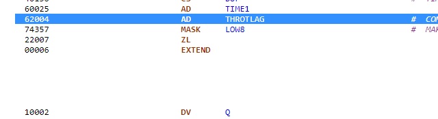 A timer "TIME1" is added to the accumulator, which keeps changing, which means that the accumulator can now contain any value. A value "THROTLAG" is also added to the accumulator. The comment says that this value is used to send the calculated command in advance so to compensate for the engine response. But this is absurd, for this value is not used to send the command in advance, but directly in the calculation of the command. |
 The command "MASK LOW8" only keeps the eight first bits of the accumulator and sets the other bits to 0; as the accumulator could take any value (after a timer has been added to it), it can now contain any value between 0 and 255. The accumulator is then divided by the contents of Q with the instruction "DIV Q"; but we have previously seen that 400 had been put into the register Q; so it means that the accumulator is divided by 400; as the accumulator can contain any value between 0 and 255 (and the register L is null), the result is 0. |
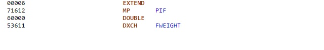 The accumulator is then multiplied by PIF, giving 0, as the accumulator was containing 0. The instruction "DXCH" then exchanges the pair of registers A,L with a variable called "FWEIGHT". |
 FWEIGHT is set to 0 at the beginning of the program P66. |
So it means that A and L now contain 0. |
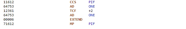 The instruction "CCS PIF" tests the contents of PIF, executes the next instruction if it is positive, the second next instruction it is null, and the third next instruction if it is negative; it means that the accumulator will be increased by one unit, except if PIF is null (but a comment says that it cannot be null); so the accumulator contains 1 after this sequence. The instruction "MP PIF" then multiplies the accumulator with PIF, and, as the accumulator currently contains 1, the result is PIF. |
 The pair of registers A,L is then divided by the contents of BUF+1, with the instruction "DV BUF+1", and it's there that we can have a big laugh, for we have previously seen that 0 has been put into BUF+1 (now you understand why you had to keep in mind that 0 has been put into BUF+1). |
 And no computer or calculator can do a division by zero, they all generate an error saying that the operation cannot be processed. Generally it makes a program stop, unless the program has provided an exception to handle this case. In any case the result is undetermined. The documentation of the AGC says that the result is then random. |
 The instruction "DAS" adds the accumulator to the variable "FWEIGHT" (the register L has been cleared with the instruction "ZL"), which contains a random value, which means that FWEIGHT also contains a random value after this operation. |
 The program then makes a call to a routine called "RTNHOLD". |
 But this variable is not defined in the fixed memory, but in the erasable memory instead; the erasable memory is only for temporary results, it contains no valid procedure. It means that the AGC is going to execute completely undetermined instructions, and there even is little chance that it could return from it. |
 If ever it returns from RTNHOLD ( a miracle is always possible), it is going to execute the following sequence of instructions. The instruction "CS ZERO" puts the complement of zero into the accumulator, that is a value with all bits set to 1 (which is called negative 0, an absurdity of the 1's complement). The accumulator is then put into PIF. |
 The instruction "QXCH" exchanges the contents of Q with RTNHOLD; Q was containing the return address of the call to RTNHOLD, so 2370 octal according to what is indicated in the listing, so RTNHOLD now contains this value. And the program returns to DOIT to make the same comedy again. |
And again we have the division by zero, giving the same undetermined result. |
 The routine "RTNHOLD" is called again, but this time we know that RTNHOLD now contains 2370 in octal. |
 The code of this instruction would correspond to the instruction RAND, which allows to make an AND of the accumulator with the contents of the channel which is indicated in the first 9 bits; but the value indicated in the first bits is 370 octal, and this is an invalid value for an I/O channel, which means that the instruction tries to accede to an I/O channel which does not exist. |
And, if even there is a return from RTNHOLD (which is little probable, but a miracle is always possible), the same comedy repeats again. |
 So, the program does not just make an incorrect job, it outright makes a completely absurd senseless job. Even if the AGC had had the possibility of sending the calculated command to the LGC, this program would not have sent it something correct. The engineers must have thought that, since it was not possible to send the calculated command to the LGC, why not have some fun with this program! |
 The routine "ATTITUDE_MANEUVER_ROUTINE" is supposed to control the attitude of the lunar module. Link to the program of the control of attitude of the LM |
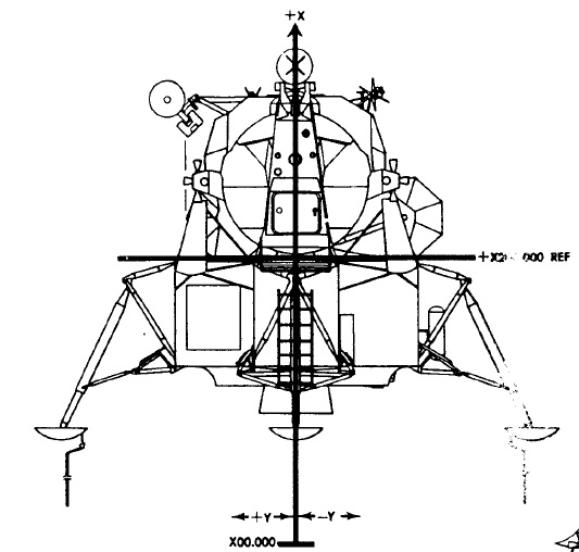 Generally, the vertical axis is called "Z", but in the lunar module, it was unusually called "X". |
 The horizontal axes were called Y and Z, Y being the transversal axis, and Z, the perpendicular axis. |
 The interface of command of the vertical thrusters had three commands, which could be either positive, or negative (so it was in fact making 6 different commands): - The pitch (rotation around the Y axis). - The roll (rotation around the Z axis). - and the vertical translation command (X-TRANSL). |
 A command of positive pitch was making the lunar module pitch upward. |
 A command of negative pitch was making the lunar module pitch downward. |
 A command of positive roll was making the lunar module roll on the right. |
 A command of negative roll was making the lunar module roll on the left. |
A command of positive vertical translation was making the lunar module move upward. |
A command of negative vertical translation was making the lunar module move downward. |
 The interface of command of the horizontal thrusters had three commands, which could be either positive or negative (so it was in fact making 6 different commands): - the Yaw (rotation around the X axis). - A translation on the right or the left - A translation forward or backward. |
 A command of positive yaw was making the lunar module turn counter-clockwise around the vertical axis. |
 A command of negative yaw was making the lunar module turn clockwise around the vertical axis. |
A command of positive translation along the Y axis was making the lunar module move on the right. |
A command of negative translation along the Y axis was making the lunar module move on the left. |
A command of positive translation along the Z axis was making the lunar module move forward. |
A command of negative translation along the Z axis was making the lunar module move backward. |
In order to communicate with the LGC, the AGC was using channels on which it could send information to the LGC, or from which it could get information from it. |
 Normally there should have existed a channel with 12 bits to send the commands for controlling the RCS to the LGC: - A bit to send a pitch command, and a bit to send the sign of the pitch command. - A bit to send a roll command, and a bit to send the sign of the roll command. - A bit to send a command of vertical translation,and a bit to send the sign of this vertical translation. - A bit to send a yaw command, and a bit to send the sign of this yaw command. - A bit to send a translation along the Y axis, and a bit to send the sign of this command. - A bit to send a translation along the Z axis, and a bit to send the sign of this command. |
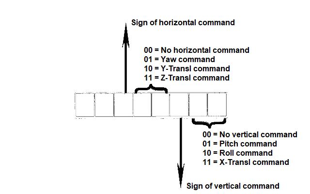 Eventually, if we consider that only a vertical command can be sent at a given moment, and only a horizontal command at a given moment, there could have been two bits to specify the type of vertical command to do, and one bit to specify the sign of this vertical command, and two bits to specify the type of horizontal command to do, and a bit for the sign of this horizontal command; that would have made twice less bits to send commands for controlling the RCS to the LGC. But, it does not seem that the LGC had provided this facility. |
 But, in fact, instead of that, there are two channels for controlling the RCS, with eight bits on each of these channels, which means that there are 16 commands sent to the LGC for controlling the RCS instead of 12. Instead of sending the normal commands of rotation and translation (three commands of rotation, either positive or negative, and three commands of translation, either positive or negative), these channels would allow to control the 16 thrusters of the RCS, what the LGC does not allow. It would make no sense that the AGC could independently control the 16 thrusters of the RCS, for nothing would prevent it from activating thrusters which are incompatible. |
 For instance, by setting the 8 bits of the two channels 5 and 6 to all ones, it would activate all the sixteen thrusters of the RCS, which would mutually cancel their effects (for they all have the same thrust); the result is that the lunar module would not react to these thrusters, while it would uselessly waste the propellant of the RCS. That shows how absurd it would be that the AGC could individually command the thrusters of the RCS, without control from the LGC. |
 Moreover, the routine which controls the attitude of the lunar module does not even write in these channels. |
This routine makes plenty of calculations which ate totally useless, for the result of these calculations is not sent to the LGC. |
 This routine essentially uses macro-instructions which are for most incorrectly specified (with two macro-instructions on the same line, which is not allowed). |
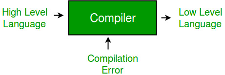 Many of the instructions of this program should not even have been accepted the compiler, which should have rejected them as invalid. |
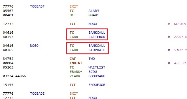 In the last part of the routine, a call is made to routines called "ZATTEROR" and "STOPRATE". |
 But all these routines do is to load variables from memory and store them into other variables. There is no access to any channel. And the routine ZATTEROR also executes a part of the routine "STOPRATE", which means that it could have been stopped before executing this part. |
And the AGC communicates with the LGC exclusively through channels, it cannot communicate with it through memory. |
And, even if there had been a channel to send normal commands of rotation and translation to the LGC, and that the routine of attitude control had written into it correct commands.. |
 ...It still would not have worked, for, in the command interface of the vertical thrusters, each vertical command activates two vertical thrusters directly opposed to each other on the same cluster... |
...Thus mutually cancelling their effects! |
So, while we have already seen above that the AGC could not control the thrust of the main engine... |
 ...We now see that the AGC could not either control the lateral thrusters of the RCS. |
 With no control of the main engine and the RCS, it was making the powered descent completely impossible. |
 And it was also making the powered ascent impossible, for, if in the powered ascent there is no control of the thrust of the main engine, the control of the RCS is absolutely necessary... |
...especially since the vertical thrusters are also needed to create a counter-torque to oppose to the growing misalignment torque generated by the shift of the center of mass as the level of the tanks gets lower, which, unlike in the descent, could not be corrected by swivelling the ascent engine, for this one was fixed, and not gimbaled like the descent engine was. |
 And, if the astronauts thought that they were heroes who were able to do the descent manually because they were realizing that the AGC was unable to do it (it could not even put the engine at full thrust at the beginning of the powered descent), it would have been doomed to failure... |
... for the problem in the interface command of the vertical thrusters would have prevented them from controlling the attitude of the lunar module... |
 ...Which means that there is no way that they could have guided the lunar module to the lunar surface, as much talented as they could be. |
 One has to be completey unaware of this fact to still believe that men walked on the moon. |
 The reality is that no one ever went through the Van Allen belts, and still less landed on the moon. |
