I. Dynamics of Disk Spacing, Geometry, Horsepower & Torque
Also -- Member Experiment in Disk Geometry
Improvement; 2002 End of the Year Review
December 5, 2002
 This
month we are going to cover the boundary layer effect and it's
relationship with disc spacing and torque. This
month we are going to cover the boundary layer effect and it's
relationship with disc spacing and torque.
We'll also briefly review what the club has
accomplished so far, and what we expect to accomplish in 2003. Finally,
we will briefly discuss our vision for using global club R&D efforts
to effectively reverse the ecological damage due to pollution and global
warming.
We're going to start out the boundary layer
discussion by reviewing a couple of emails sent by club members.
Greg Rogers writes about disc spacing:
"You state that you used a spacing of .125 inch between discs of the turbine
when you compared your design to Tesla's design. However Tesla's design used
spacing of around .03 - .04 inch. Using as high spacing as you are using you are
not operating as a Tesla turbine but rather a centrifugal turbine using the
action of buckets or wing shaped blades in your case. Also on your site some guy
stated that the spacing needs to be even smaller than .04 inch which is around 1
mm. That the discs must be spaced closer to .1 - .25 mm, thus requiring high
precision to take true benefit from the design."
Also, Peter C from Long Island, New York writes:
"I am working on a 12" dia x 45 pound Tesla turbine. I have a good idea
of how to calculate HP based on dia., rpm, weight, etc. However when it comes to
torque, I understand the concept but do not know how to calculate it on paper or
measure it on my rotor shaft. Is there a "torque meter or devise" that
indicates quantities of foot-pounds? (Besides my old automobile torque wrench)
Can someone help me? Thanks -- Peter C."
Comments
 First
of all we'll look at some of Nikola Tesla's historic experiments to get
an idea of the relationship between disk spacing, horsepower, torque,
and efficiency. Tesla started out building a 6-inch turbine followed by
a 12-inch, 9.75-inch, 18-inch and finally a 60-inch. With the smaller
turbines he used a disk spacing of .03 inches (0.8mm), with disc
thickness the same (.03"). First
of all we'll look at some of Nikola Tesla's historic experiments to get
an idea of the relationship between disk spacing, horsepower, torque,
and efficiency. Tesla started out building a 6-inch turbine followed by
a 12-inch, 9.75-inch, 18-inch and finally a 60-inch. With the smaller
turbines he used a disk spacing of .03 inches (0.8mm), with disc
thickness the same (.03").
Once he moved to 18-inch diameter disks, he
increased both the disk thickness and spacing between them to .0625
inches (1.6mm). While working with the Allis Chalmers company of
Milwaukee, Wisconsin, his largest design -- a 60-inch diameter turbine
-- was built using a disk thickness and spacing of 0.125 inches (3.2mm).
Tesla's 10-inch turbine produced 110 horsepower,
his 18-inch produced 200-300 hp, and the 60-inch produced 675 hp. Tesla
also mentioned in his aircraft designs that for maximum efficiency the
exhaust port should be reduced, but for maximum horsepower the exhaust
size should be increased. In addition, Tesla stated that the greatest
efficiency is achieved when the disks rotate at the speed of the fluid,
but maximum torque is realized when the disks rotate at just over 50% of
the fluid speed.
Other factors that affect efficiency and power are
the same as those affecting aircraft, cars or any aerodynamically
sensitive object: surface finish and geometry.
To put it plainly, it is virtually impossible to
calculate the obtainable torque and horsepower due to aerodynamic
complexities; however, if you follow the basic design and construction
methods already established, you will achieve results that are
relatively close to Tesla's experiments.
Quoting from Tesla's own patent:
"Owing to a number of causes affecting the
performance, it is difficult to frame a precise rule which would be
generally applicable, but it may be stated that within certain limits,
and other conditions being the same, the torque is directly
proportionate to the square of the velocity of the fluid relatively to
the runner and to the effective area of the disks and, inversely, the
distance separating them. The machine will, generally, perform its
maximum work when the effective speed of the runner is one-half of
that of the fluid; but to attain the highest economy, the relative
speed or slip, for any given performance should be as small as
possible. This condition may be to any desired degree approximated by
increasing the active area of and reducing the space between the
disks."
If you start with disk spacing that is optimal for
a particular working fluid viscosity, then the torque is directly
proportional to the square of the working fluid velocity, relative to
the disk speed, and relative to the effective area of the disks.
Also, as the disk diameter decreases, torque drops
off exponentially. If you decrease the disk diameter by half, the torque
drops off by a factor of four, but the disk speed increases by a factor
of two.
While some theoretical calculations project a
yield of only 2-3 horsepower for a 10-inch disk, the effect of the
working fluid is obviously being overlooked. The best way to begin
figuring horsepower and torque is through empirical (experimental)
process.
Tesla recorded approximately 110 hp for his
10-inch (9.75-inch disk diameter) turbine using 25 disks at 175 pounds
of steam pressure. Even though he didn't record actual torque specs,
theoretical calculations for boundary layer disks show an exponential
increase of torque over horsepower.
In other words, as the horsepower doubles the
torque quadruples.
Assuming a 10-inch turbine delivers approximately
110 hp, the torque would theoretically be in the neighborhood of
approximately 216 newton-meters. Since 1 Nm = 0.7376 ft. lb., this
translates into about 160 foot pounds of torque. This
horsepower-to-torque relationship follows typical turbine
characteristics; the 1987 Chevy turbine experiment resulted in a 120 hp
bladed design delivering 350 ft. lb. of torque.
One last piece of the puzzle we need to examine is
the aerodynamic effect of the disk geometry.
First of all, we want gas adhesion to the disk
surfaces to be as great as possible -- which means the disks must be as
highly polished as possible. Imperfections in the disk surface cause
vortices in the gas flow, resulting in lose of adhesion, and lower
energy transfer efficiencies.
Next we have to consider the maximum boundary
layer dimensions. An excellent study on the subject is H. C. Smith's
Illustrated Guide to Aerodynamics. On pages 57-60 he covers the
dynamics of the entire boundary layer, including the laminar region and
turbulent region. On page 60 Smith states that the laminar region
extends to 0.03 inches thick, or double that (0.06 inches) for two disks
placed next to each other. He goes on to say that the transition layer
is about 0.1 inches thick, with the turbulent region as thick as 0.5
inches.
Theoretically then, a Tesla turbine will still
work with up to 1.0 inch gap between the disks -- with greatly reduced
torque. That explains why his turbines continued to work well even with
a 0.125-inch spacing. To compensate for the torque loss, the diameter of
the disks must increase as the spacing increases.
Since larger gaps allow turbulent regions to
operate, the energy transfer mechanism shifts from adhesion to turbulent
parasitic drag. Of course, the fluid properties, pressures, etc. have a
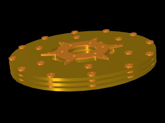
lot to do with laminar vs. turbulent flow also. Tesla used round washers
around the periphery of the disks to assist in spooling up the turbine;
these washers work on a strictly parasitic drag principle and are
absolutely necessary to get the turbine moving when the gas
back-pressure (due to centrifugal force) is at zero.
One last thing to consider is that if the spacing
between the disks becomes too small, an aperture closing effect causes
the high velocity gas to go around the disk pack rather than through it.
That's also why spacing between the disks and housing must be kept at a
minimum -- or provide labyrinth seals to prevent gas blow-by.
In conclusion, for a 10-inch turbine, disk spacing
anywhere from 0.03 to 0.0625 inches is ideal, with 0.125 inches
tolerable with larger (48-inch to 60-inch) turbines -- torque being the
factor to watch.
Ken Rieli
|