SUBLIME3
This report has been a little while in the making, but allot was acomplished! I finished one side of the drive, and I can say doing a double reduction through chain drives has been a challange!


In the last report I finished by connecting the front tires to the back with some #25 roller chain. Now I needed to build a 5:1 gear reduction system for my robots drive motors (which happen to be the popular EV warior motors) I decided on a double reduction system done through chains, I found a score of surplus sprockets, roller chain, and bearings so I went to work! I started by taking a chunk of 6061 alluminum and cutting it down in the bandsaw, the final size was 1" buy 4" by 3". This block will become the chain reduction housing.
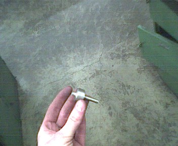

I milled a pocket in the the peice of alluminum, then did a quick layout test, everything fits! Here is the nifty axle I turned up for the big and little sprockets to sit on in the gearbox, notice it has a small 1/4" shaft on one end, that is suported by a ball bearing in the back of the gear box housing. The long 1/4" part will stick out of the gear box, and a small sprocket will be mounted to it to transfer power to the tires.


This gear box is also going to do double duty as the motor mount, so I had to come up with a way to mount a motor that has no easy way to mount it. My solution was to tig weld two bolts to the face of the motor, I will not be showing pictures of the procces as it can damage your motors easily if done wrong... To finish the gear boxes I needed to make a front cover, I took a long chunk of 3" by 1/4" 6061 alluminum and cut it to size on the hydralic shear. I then drilled a hole in it so the bolts welded to the motor could pass through, and for a bearing to support the axle coming out of the gear box to be pressed in. I then pressed in the 1/4" ball bearing in to get the complete front plate for the housing.


After lubing up the chain and sprockets I bolted the gear box together, Here it is done. I needed a sturdy way to mount this to my robot's 1/4" base plate. So I drilled, and then taped the gear box so I can mount it with two 3/8" bolts.


I decided to test run the gear box, so I pluged the motor into one of my super cool Victor 883 speed controlers, and gave it a test spin, runs really smooth! I laid the gear box on the base in it's aproximate final position to see if it would fit, it did. I then drilled holes in the base to provide clearance for the two 3/8" bolts the hold the gearbox/motor mount down. After this I bolted the gearbox/motor on and put the #25 chain fron the 8 tooth sprocket on the output shaft of the gear box, to the 16 tooth one on the axle


Here is another shot of the finished setup. The chain connecting the front and back tires is so close to the base, it actually touches in the middle. This won't do so I cut out a chunk of UHMW plastic to make the chain guide.


I milled a slot in it for the chain to slide through, them mounted it to the base in the centered between the two sprockets. Here is the base on the ground of my metals shop for a test roll, smooth! That is all I got done in this report, I will machine up the other side, then take it for a test drive in the next report!

