Space Elevator - Development Visions
(Eric Hunting - hunting@tigger.jvnc.net - 9/4/02
I've been developing a vision and scenario for an SE project and I thought
I might share it with the group. It might be useful in focussing discussions
if there was a specific project scenario whose components could be individually
analyzed.
System components:
Initial Tether and Deployment Rig:
The initial tether would be fabricated on earth and would consist of a
very thin nanofiber cable or ribbon -around a centimeter thick/wide at the
ends- which would be carried whole to orbit as a pair of coils. The coil
carrier would consist of an octagonal space frame truss girder made with
a ball-socket node truss system -such as the one Star*Net Corp. developed
for the ISS but which was shelved by NASA- inside which the tether would
be coiled in two coils in an outside-in manner like rope coiled in the storage
space on a sailing ship. Two deployer rigs are mounted inside the ends of
the truss along with terminator modules; instrument packages in a capsule.
The 'up' module would house sensors to aid deployment tracking, monitor tether
electrical/electrostatic potential, and so on. The 'down' module would feature
a streamlined capsule with telemetry transponders and small deployable fins
-a set of small square ailerons on thin pop-out struts- which allow it to
be steered in winds. Between the two coils is a clamp rig with neprene sheathed
clamps which grip onto the tether. On the outside of the truss would be
retrofit attitude control modules, deployable solar panels, a command and
telecommunications package, and possibly a light telerobotic arm.
This structure, which I imagine as approaching the size of a Shuttle EFT,
would be launched whole using a launch system which is retrofit to its sides.
One launch concept I favor is the use of a dirigible airship assisted launch
system. This would take the form of a large ballonette hull with a lenticular
ovoid shape (think a rounded edge disc stretched into a slender oval) made
from a space frame of pneumatic struts. (pressurized membrane tubes with
socket connectors on their ends. Made from the same material as the tether
and highly pressurized, these would be as strong as solid aluminum yet an
order of magnitude lighter) It would include its own short duration fuel
cell power supply and ducted fan thrusters intended for attitude control
but no propulsion at speed.
The truss package would attach to this hull like a gondola. Attached to
the flanking sides of the truss package would be one or two conventional rocket
boosters, most likely solid fueled. The airship hull would lift the launch
package to a very high altitude, transitioning from gas lift to vacuum lift
at high altitude in order to give the vehicle the maximum possible altitude,
hence the use of a dirigible structure rather than a simple blimp. Vacuum
lift is not possible with existing materials at sea level air pressures
but at very high altitude where air pressure is very low a dirigible made
with conventional materials could shift to vacuum lift, discharging lift
gas with altitude as normal high altitude balloons do but continuing until
evacuated, gaining about an extra 10-20% in altitude. Upon reaching this
maximum altitude and positioned for an equatorial launch, the vehicle would
ignite its rockets, ramping up comparitively slowly in speed. Upon reaching
sufficient airspeed, the dirigible ballonette is jettisoned and the vehicle
accelerates to a GEO velocity, later jettisoning the spent rockets. The
dirigible hull could be recovered for later re-use but the system is generally
not intended to be reusable.
The point to the airship assist is to get the truss package to an altitude
where there is very little atmospheric drag so that it can be launched without
the added mass of a streamlined skin. There is a small but not entirely
insignificant savings in rocket power from eliminating the drag encountered
from sea level but since a conventional vertical launched rocket only sees
maximum drag for a tiny amount of time during launch, that by itself would
not justify this approach. What it's really about is saving net vehicle mass
by using simpler and lighter construction. The less sheering force stress
from drag, inertia, and engine vibration the vehicle must withstand during
acceleration the lighter and less robust its construction can be. Thus it
becomes practical to use simple modular components for everything and to
eliminate the extra mass of a streamlining skin. Space structures rarely
need the robustness of construction that is typically employed. This robustness
is largely just to compensate for the stress the structures endure during
launch. Reduce that stress and you reduce the whole mass of the system. Also,
conventional rocket engines only operate efficiently in a small range of
air pressures and for a sea-level launched rocket a lot of efficiency is
lost because the engines must transition between such a wide variation in
air pressures. Launched at high altitude, a rocket engine can be optimized
for near-zero air pressure alone, thus leading to a simpler lighter engine
with higher efficiency, which means less fuel and thus less net mass.
So basically this 'gimmick' allows you to build a whole launch system from
cheap ultralight space frames and simply assembled modular retro-fit components
that normally might not tolerate the conditions of launch. Plus, you get
the ability to launch a relatively large and fragile payload with the minimum
of physical stress, the ability to abort and recover the whole payload package
at any point up until the ballonette jettison point, the freedom to deploy
a launch vehicle from anywhere without elaborate permanent ground facilities
using the airship component as a shuttle to the equator (remember, the bulk
of launch costs are on the ground, not in the vehicle), and you avoid launch
delays associated with weather because in the stratosphere there is none.
The package could also be launched in a more conventional manner, using
two to four booster rockets and an added nose cone, tail blast sheild, and
aluminum streamlining skin on the spool package. The carrier space frame structure
would have to be tougher and much more expensive overall but its basic form
could remain the same, though a lot of the added 'packaging' has to be dismantled
on orbit using robots. A likely configuration could be a ring of Zenit boosters
or similar simple rockets.
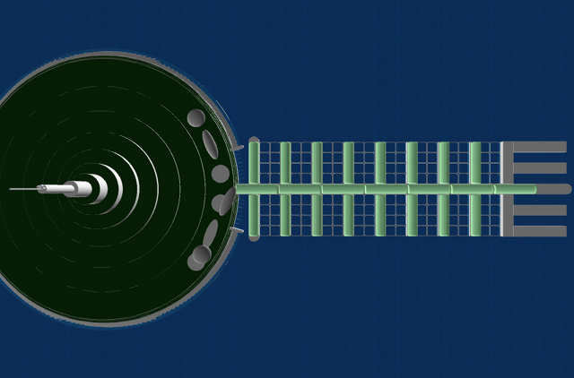
GEO Upstation:
The space frame truss used for the tether carrier package is the foundation
of the initial GEO facility and this role is largely the reason for its
space frame based design. This structure would serve as an expandable scaffold
onto which all the later facilities in orbit would be retrofit simply by
plugging into the space frame nodes or clamping onto its struts. Similar
to the MUOL (modular unmanned orbital laboratory) concept, it would host
a 'backplane' system which integrates fiber based communications, power,
and thermal radiant fluid supply using a utilities module that retrofits
to the inside of the truss and allows structures retrofit to its outside
to plug in via standard ports, just like components plugging into the backplane
of a computer system.
The communications system for the Upstation backplane would be based on
a pair of IP networks using a conventional microwave link to the Downstation,
one dedicated to the systems management of the Upstation, the other a 'community'
network shared -through VPN subdivision- by Upstation lease space clients
for communication between their individual service packages/modules. The
standard architecture of the Upstation's systems would be based on the use
of integrated Web controllers. These are microcontrollers which have a built-in
single-chip Web server which presents a virtual control panel that can be
accessed from any point in the system's network. Technicians manage the station's
systems and client packages by paging through the virtual control panels
or by using hierarchical control panels which, through a single interface,
manage multiple controllers using the same Java messages. Complex automated
sequencing is also possible in this way, but using independently running
sequencer programs running on master management computers on-board or on-ground,
allowing for the same technology to also be used as the basis of complex
launch sequencing, experiment management, or later spacecraft operation.
This can be employed to reduce the development and operational costs for
new launch systems, like dirigible hybrid vehicle proposed above. In essence,
the Upstation is a kind of MUOL. (for background on the MUOL concept see;
http://www.distant-star.com/issue13/jan_2002_leo_or_geo.html
)
This core truss must freely expand in width with the incremental expansion
of the thickness of the tether as well as host a perpendicular planar space
frame on which lease space components can be located with a clear terrestrial
(or less frequently a clear space) view. Construction of this plane space
frame would be one of the first orders of business for the Upstation and
part of the initial truss package could include a telerobotic manipulator
arm similar to the MK Robotics Canada Arm deployed on the ISS to facilitate
its assembly. Thus the geometry of the core truss must synchronize with the
geometry of the surrounding plane truss. This means that the core truss must
fit into a 'tesselation' of the plane truss derived from the same component
geometry. Thus it will likely use a cubic space frame based on two strut
lengths that allows for an octagonal core truss to intersect a rectangular
planar space frame. This would be consistent with the cubic unit module geometry
for lease space components envisioned in the MUOL concept. The size of the
intersecting octagon can increase in face size in units equal to the width
of the cubes of the planar space frame. Thus expansion of the core truss
would be performed simply by clearing any functional plug-in modules at the
intersection of the core and plane trusses, building a new core truss around
the old one, and then disassembling the old core truss from inside, the old
parts recycled by expansion of the plane space frame. This process can be
conducted indefinitely, no matter how large the tether becomes. But as the
structure grows the plane truss will need to be thickened as it increases
in area to increase its rigidity. Thus after several stages of growth the
core truss will becomes completely absorbed into the plane truss, which will
have thickened to become a vast rectangular space filling frame through which
the tether passes.
Manned habitat structures would take the form of trans-hab-like inflatable
modules surrounded by the spaceframe to which radiation and meteroid sheilding
panels would be attached, all designed to be assembled on orbit from densely
packed modular parts that would be relatively easy to convey along the rudimentary
tether. This is the most efficient approach to habitat construction, since
there is technically no reason for sheilding materials to be integral to
a pressure hull and with membrane structures capable of packing exceptionally
large habitat volumes into very compact packages. (a space station based
on transhab technology could fit the entire inhabited volume of the finished
ISS into a single Shuttle payload. In fact, this was planned early in the
Shuttle program but shelved. Smaller transhab modules similar in size to
the existing ISS modules should readily fit within the payload capacity of
second or third generation climbers)
[Transhab prototype design]
Most likely, the initial GEO Upstation would host a 'crew' composed exclusively
of compact teleoperated robots, the initial tether conveyors -due to the
small scale of the initial tether- limited to carrying components of small
mass. Non-pressurized shelters in the form simple shielded box enclosures
and pressurized shelters in the form of small modular pressure vessels with
external support equipment would be the typical facilities for a long time.
With communications latency low for a GEO facility, telerobotics is relatively
easy to implement and so human workers in space would be unnecessary, and
not cost-effective in any case. Indeed, the only commercial space activity
that actually requires any manned facilities is tourism, though once the
full scale elevator transport is in place the ease of transport may make
human workers more cost-competitive.
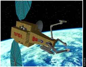
[NASA Ranger telerobot assembler prototype]
It is also possible that manned habitat facilities at this GEO Upstation
could be provided by the hollow fuel tanks left from the original tether
carrier package boosters -assuming they were LH/LOX fueled. The tanks could
be pre-adapted for this purpose with pre-installed partition and frame sockets,
hatches, and windows behind conformal tank skin plates. However, that's much
extra mass to carry to GEO and with the GEO station remaining unmanned for
a long time these would have to remain mothballed on orbit for many years.
Later generation Upstation facilities would become increasingly integrated
into the structure of the tether itself, depending on which of the tether
development approaches noted below is used. Manned facilities would evolve
to become incorporated into the vast volume of the tether at its thickest
center portion, using a matrix of internal channels which, by virtue of
the tether composition, already offer an impermeable structure that need
only modular caps on the exposed surface channels to make them pressure-tight.
The considerable mass of the tether material itself would be relied on as
radiation shielding. In the case of the multi-strand approach noted below,
the same transhab-like structures would be used but suspended in the matrix
of discrete tether strands rather than attached to an external space frame.
External systems -primarily communications, solar and radiator panels, solar
dynamic systems, and spacecraft assembly/service 'creches'- would be attached
to unused elevator rails in a fashion similar to components on a T-slot
profile beam or may rely on external truss booms clamped on in the same
way or extending from the surface ends of interior channels.
Tether Climbers:
Initial transport along the tether and incremental addition of fiber strands
would be based on 'climbers' that use simple membrane LTA lift cells for
initial lift then traverse the cable by traction drive using polyurethane
wheels when they reach the stratosphere. These small vehicles would take
the form of a segmented tensegrity (cable-stayed) truss chassis to which
the drive hardware is bolted facing the inside and payload, lift cells, and
drive/control components on quick-release locks on the outside. Vehicle mass
would be greatly minimized using a tensegrity truss structure -exploiting
the same materials the tether itself is made from in the form of cable stays
and composite compression rods. The vehicle would be held together by tiny
explosive bolts which are intended to snap its cable stay links and cause
it to break apart completely in the event of it getting stuck on the tether.
These climbers would have small payload capacity and could be powered either
by inductive energy from the cable, by photovoltaics, or beamed power using
IR laser (feeding IR PV cells) or microwave beam. In the case of these beamed
energy arrangements, the use of a lenticular (disc shaped) LTA hull around
the climber would provide support for these power systems energy collectors,
either covered by flex-cell IR PVs or being covered with an elastomeric laminate
rectenna array for microwave pick-up. The round shape also serves well as
the basis of a coil storage platform, allowing the climber to add fiber to
the tether from another outside-in coil surrounding the tether coiled inside
the chassis truss much like the tether was originally coiled on the GEO truss
package.
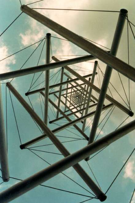

[a tensegrity truss mast, made as sculpture]
A possible alternative to the use of polyurethane wheels in the climber
drive mechanism could be a kind of dual tractor band. This would consist of
two flat soft plastic (neoprene?) bands on carriers similar to a tank wheel
track or conveyor belt which sandwich and clamp the tether between them when
engaged. The advantage of this system would be a very high friction interface
between drive and tether that eliminates slippage that would result in wear
on the tether fibers -important considering the hundreds of thousands to
millions of trips these simple climbers would make during the incremental
construction of the tether. However, it could be a much slower and heavier
drive mechanism.
There is also a possibility of exploiting electrokinetic thrust 'lifter'
systems for a climber drive if the tether itself is capable of providing
the high voltage from electrodynamic induction this propulsion requires.
The ultralight tensegrity climber chassis would be well suited to this kind
of propulsion. At high altitudes and in space this would require the use
of ducted field grids with some means of intake compression like fans and,
above the atmosphere, a supply of compressed gas propellent. This added drive
hardware mass could be a problem for this concept. If viable, this would
offer a very high speed non-contact way of climbing the tether using solid-state
hardware with a potentially supersonic speed and 5:1 ratio of payload to
drive mass. (assuming externally provided power... EK lifters would be completely
infeasible if they had to carry their own power source) These would be too
fast and light to function as a tether fabricator. They would, instead, be
limited to quick light transport alone -and very light transport at that.
Whether these devices could work for a full-scale elevator is unknown. At
present the technology is at a Wright Bros. level of development with largest
model vehicle ever built only a couple meters long. So it's safe to speculate
for a small climber but perhaps not for a large elevator car.
Full scale elevator system:
This will likely emerge quite some time after the initial tether deployment
due to the period of time required to incrementally thicken the thin initial
tether to a scale where it can bear the necessary mass. The target form
factor for the full scale elevator will likely derive from existing terrestrial
transportation systems. This means that dimensions will likely derive from
the dimensions of the largest standard marine shipping container; 40'x8'x9.5'.
Indeed, it is possible that the elevator design would use a variation of
the standard marine container built of nanofiber composites and attaching
to a modular elevator chassis via quick-connect locks allowing for direct
intermodal transfer. Thus a fair guestimate for a basic minimum elevator
car size would be 50' tall by 15' wide.
The full scale elevator will most likely rely on a linear motor drive using
magnetic isolation (keeping it from contacting the track it climbs) and
will assume one of three likely configurations depending on which tether
structure is chosen; monorial, mono-cable, and tubular. The monorail configuration
relies on an external track either in a T-beam or T-slot form, the drive
chassis surrounding the track in the case of the T-beam or riding whole or
partly inside the track in the case of the T-slot. The elevator car rides
parallel to the track and is readily accessed externally. Most SE schemes
have been based on this elevator configuration but its drive design is complex
because of asymmetric axial loads on the track.
The mono-cable scheme relies on the use a tether strand dedicated exclusively
to the task of carrying one elevator car. The tether functions as the track
and the drive chassis surrounds it, being either fully enclosed by the elevator
car or with the car divided into modular components attached and balanced
around the core chassis. This configuration derives from that of the simple
climber and would have the simplest drive mechanism. But the configuration
is complicated in terms of cargo handling unless the net car diameter is
very large -perhaps 50' wide. There are also failure scenario issues with
this configuration, which will be discussed later. Car size is also limited
by the scale of its tether track, regardless of the scale of the whole tether
structure.
The tubular configuration relies on a surrounding tube as a track with
the drive system surrounding the vehicle. This is a very simple drive configuration
which offers simple asymmetric axial load compensation. But this approach
requires the tether to assume a relatively complex corrugated form with
multiple tubes. This, in turn, requires perpendicular channels to be formed
to access the elevator car or for the lower tether terminus and mid section
to be 'spread' apart into multiple strands so that the interior tubes are
opened up for whole-car access. A fixed elevator car size regardless of the
ultimate tether scale is another limitation.
Tether fabrication and structural approaches:
Incremental expansion of the tether would be performed by laminating thin
fiber tape windings to the cable -flat or round- using slow climbers. Each
added tape winding represents only a miniscule mass compared to the cable
itself, allowing the applicator climber to travel first to the GEO point,
or it's last application point, then use gravity (or centripetal force on
the above-GEO tether length) to pull it along as it laminates new material
to the tether. Later tether material fabrication would shift to the Upstation
which makes the transport of building material easier since it can be piped
to the Upstation through a hollow core tether in the form of carbon monoxide
gas. Each phase of lamination consists of layering short strips over the
middle tether regions followed by progressively longer strips to the ends.
This insures that the tether is made thicker toward the middle than at the
ends, since the middle experiences the highest degree of tensile force. This
laminating is a necessarily slow process, each new layer of tether material
taking perhaps months to apply. This creates a certain conflict between the
revenue-generating use of the tether and its incremental expansion which,
of course, expands the payloads the tether system can communicate between
Earth and space. The solution is to develop the tether structure so as to
support multiple simultaneous uses; material laminating, retrofit structural
support, and elevator track.
There are three likely full-scale tether structural approaches; monolithic,
corrugated, and multi-strand. The monolithic full-scale tether -the type
most commonly suggested in SE schemes- is based on a prism structure with
polygonal cross section which is intended to allow different prism faces
to assume seperate functions. The initial tether could be flat or round but
in either case would evolve to assume a 4, 8, 16, 32, etc. sided section.
Sides are expanded alternately, using a variation of the climber which travels
on one or two tracks while laminating the face adjacent or in-between. As
each face completes a phase of laminated expansion it is 'finished' by the
addition of a conformal elevator rail structure made of the same tether material.
This might take the form of a T-beam which is stripped off or fully absorbed
into the tether with successive expansion or a T-slot which is closed off
with each phase of expansion, producing a relatively thin corrugated structure
in the tether section to be used as pipelines and power/communication vias.
When not being worked on by a laminator climber, each free side becomes
available to carry either an elevator vehicle or host demountable structures
which clamp onto the track.
The upside to this approach is that the fabrication process is relatively
streightforward. The downside is that the initial tether has to be expanded
to a pretty large size before it assumes a polygon side width large enough
to host a useful elevator track. Until then, the tether project is limited
to alternating cycles of tether expansion and tether transportation -since
it's complicated for climbers using continuous contact traction to pass
over each other on the tether. It also can't host any intermediate station
points, again because the climbers can't easily pass over the station structures
unless they are very large, wide, and light. And even when it can start supporting
these structures, they would be limited to very narrow forms in order to
allow enough room for elevators and climbers to pass by them.
The corrugated tether approach is based on the use of an internalized elevator
system and hence the tether would assume the form of a series of parallel
hollow tubes as it grows. This would be done by first expanding the initial
tether monolithically until it can support the mass of ultralight inflatable
super-pressure forms made of the same tether material which the climbers
tape over to make the hollow space. The balloons are then cut away from the
inside to create a shaft into which elevator track hardware is retrofit.
Once the first tube is complete, it can host its elevator internally while
externally the laminator climbers continue to expand the structure uninterupted.
Any number of parallel tubes can thus be formed in place to support different
jobs; elevator, pipeline, communications vias, internal habitat space.
There are a number of compelling advantages to this approach. First, it
is easier to engineer a linear motor drive when the drive mechanism is arranged
radially around the vehicle. This is because the axial loads around the
vehicle would be uniform. With an external track vehicle, there's a difference
in axial loads between the top and bottom of the vehicle which the drive
carriage or aerodynamic form of the vehicle system must compensate for in
some way. This is because as the vehicle accelerates drag on the capsule
plus gravity and intertia create a shearing force that wants to pulls the
top of the car away from the tether while the bottom is alternately pushed
in. And when the vehicle decelerates via breaking this force is reversed.
This is not a problem for the internal elevator which is completely surrounded
by its drive mechanism and under a radially uniform drag, gravity, and inertia
force. Such an elevator system would easily translate into a mass accelerator
launch system, allowing the elevator capsules to be launched from the end
of the tether with massive acceleration.
Another advantage is that as the tether structure increases in volume tubes
at the center enjoy increased radiation shielding by the material of the
tether itself. This means that one can use core tubes for human transport
and outer tubes for materials transport while still having the same basic
elevator vehicle and without spending extra mass on sheilding for human passengers.
Related to this is the fact that a very thick tether with numerous redundant
tubes may also allow virtually all human habitat space needed for the GEO
station to be internal to the tether itself rather than based on external
structures. Numerous parallel tubes also provide numerous conduits for supplying
all kinds of gaseous materials, power, communications, and other applications.
With a little imagination, some very interesting and novel applications
for these tubes could be devised. For instance, a tube could be used as
a huge tornado tower by simply leaving its end open to space. The difference
in temperature between sea level and space create a vortex along its length,
which would be tapped as another source for power via in-line turbines or
just light field coils exploiting the magnetohydrodynamic potential of the
moving air. (insignificantly small in a small tunnel but along the whole
length of the in-atmosphere portion of the tether potentially a lot of energy)
Similarly, linked pairs of tubes could be used to create a thermal cycle
between the cold Upstation side and the warm Downstation side, creating a
continuous updraft that could produce power or be used simply as a means
to pump gasses to the upstation. If the updraft were powerful enough, it
might actually power a pneumatic elevator.
The downside to this structural approach is that the fabrication is more
complicated and, with no external rail system to travel on, the laminator
climbers must increase in width to accommodate the increasing thickness
of the whole tether. Intermediate stations must retrofit temporarily inside
the space of unfinished tube sections and cannot expand outside the tube
volume in order to allow the climbers to pass over them. Window views are
eliminated inside the elevator and limited to the ends of cross-shafts for
internal habitat structures, those these can potentially be quite large.
The size of elevator cars becomes permanently fixed by the dimensions of
the tubes, compelling the initial tube to assume the largest reasonable dimension
for an elevator cab, and it is not possible to transfer payloads which might
be low mass but bulky and larger than can fit inside the tube. Transfer between
tube and station becomes a complicated affair, especially at the Upstation
where the great thickness of the tether means that long access channels
must penetrate the tether. Or the tether must be spread apart into multiple
sections to allow for numerous access channels.
The multi-strand approach is based on the idea of using multiple duplicates
of the initial tether in order to create a network of thin tethers rather
than a single tether. This is achieved by assembling or launching duplicates
of the same tether carrier package used in the initial deployment, attaching
them to the Upstation truss structure, and using climbers to guide the new
tethers up and down with the adjacent tether serving like a track. Technically,
there is no particular structural reason why the SE tether needs to be one
monolithic cable. A matrix of cables will bear the same net loads.
The primary advantage of this approach is that the SE project could quickly
support simultaneous transportation -and hence robust industrial applications.
Multiple tethers make it easy for the project to support multiple simultaneous
activities, each individual tether dedicated to a single task. Fabrication
of tethers by lamination is MUCH faster when it can be done in a factory
setting rather than on the surface of a deployed tether. So a matrix of tethers
would be faster to make than one monollithic tether of the same mass. And
by using a matrix of thin tethers as scaffolding and materials transport,
a very large tether can be simultaneously fabricated and deployed within
them -the scenario envisioned by Arthur C. Clarke in Fountains of Paradise.
Alternatively, multiple initially independent tethers can be mechanically
bound together to make a thicker structure, either monolithic or corrugated.
The use of the tether itself as a station structure becomes more practical,
the matrix of tethers serving like the system of columns in a typical skyscraper
onto which truss supports can be simply clamped. The SE could readily evolve
into a kind of superskscraper this way. Full scale elevator systems can evolve
more directly from the initial climber technology, the engineering greatly
simplified by using the whole tether as a centralized track and drive mechanism.
Upgrading to superior tether materials is a simple process, as individual
tethers can be obsolesced and removed with the rest of the SE structure remaining
unaffected. Likewise, failure of individual tethers would not effect the
rest of the structure, except where its failure causes damage to retrofit
structures.
The downside of this approach is that low net load capacity of small individual
tether strands would demand any fixed retrofit structures to be of extremely
low density, which may limit their usefulness. Likewise, limited to a thin
tether moving through its center as a track, elevators for this type of
system may always be limited to extremely low capacities and face cargo
packaging problems from the obstruction of the center drive structure. Instead
of a unified car structure, a modular structure where a core truss drive
chassis is surrounded by relatively small cylindrical component modules
is more likely. Less surface area for the car to ride on means greater potential
tether damage in the event of elevator drive failure. Total tether failure
is much more likely, and if the falling elevator car is inside the tether
matrix, much damage to other components is likely. It is much more likely
for debris from this sort of elevator to be guided by the other tethers
around it so that it is dropped right THROUGH the Downstation like a bomb,
rather than being thrown away from the tether and Downstation by coriolis
forces. This by itself may limit these elevators to a very small size.
Considering the long period of construction the SE is likely to face, later
nanofiber fabrication employing mechanosynthesis (ie. nanomachine fabrication)
techniques would likely emerge while the tether is still in a relatively
early stage of development. This would at first be employed in the factory
based fabrication of laminate tapes on orbit but would later be employed
more directly for the in-situ fabrication of the tether. This third generation
technology would likely take the form of a nanolaminator climber. This would
be similar to the conventional laminator climber except that it would carry
no reels of tape. Instead, it would feature a pneumatic collar with integral
radiator fins which would fit around a section of the tether defined by the
spacing of built-in gas supply ports on the face of the tether. Filled with
a slowly circulated fluid medium, this collar would host a 'culture' of nanoassemblers
which pick up CO molecules from a gas permeable plate on the gas supply
port and plug them into the nanofiber matrix on the surface of the tether
structure, producing an extremely uniform nanofiber structure. The climber
would move in sections down the tether, applying perhaps a millimeter of
material in each section. A fleet of these nanolaminators could work in
series, continuously thickening the tether at a great rate.
A fourth generation technology would take this even further, allowing the
tether to grow its structure uniformly allong its whole surface simultaneously
while also providing its own raw material. This would take the form of a
nanomachine sheath composed of a network of self-interlocking nanostructures
which create a self-expanding corrugated sheet. Along the lower in-atmosphere
section of the tether this sheet would sport an array of fin projections
or corrugations. These are covered with a molecular collector surface which
scrubs carbon dioxide from the ambient atmosphere, cracks it into carbon
monoxide and conveys it to a CO supply line inside the tether. On the inside
of this sheath the corrugations are filled with fluid hosting nanoassemblers
which use the collected carbon monoxide to assemble nanofiber in successive
simultaneous strip sections equal to the corrugated channel width. The corrugation
also allows the sheath to function as a radiator. As each strip of material
is added, the sheath expands in radius by dividing its corrugations, exposing
unfilled sections of tether surface to the assemblers. In this way the entire
tether slowly thickens uniformly and continuously, extracting its raw material
right from the atmosphere.
Both these later generation technology approaches would favor either the
corrugated structural approach -since this leaves the whole exterior surface
of the tether free while it is used for transport internally- or the monolithic
tether approach, with some relatively minor adaptations to the fabricator
configuration needed to accommodate alternate face growth.
Downstation:
The initial downstation structure would take the form of a Pneumatically
Stabilized Platform made of concrete, as developed by Float Inc. of California.
The reason for this choice is that the PSP is a low cost, modular, and self-mobile
structure which can be mostly built on-site and affords a high degree of
stability by virtue of its ability to consume all wave energy of wavelength
shorter than the platform width. It can also exploit this energy for electric
power using turbines in the inter-cell ductwork of the platform, though on
the equator relatively little power would be produced due to the calmness
of the seas -hopefully enough for station-keeping alone. Using active station-keeping
based on electric azimuth thrusters, the PSP is more stable than any floating
oil rig and, because it functions as its own breakwater, readily provides
the downstation with the ability to support large ship mooring along its
edges. This is a critical capability, since the only way cargo and personnel
can be transferred to an oil rig platform is by crane, helicopter, or cable
shuttle.
But more important, the PSP would be incrementally and indefinitely expandable,
able to maintain and expand its structure using construction facilities
on-board. This allows for maximum exploitation of the resources the space
elevator would afford in direct proportion to its scale of transport during
its incremental expansion. As development of the tether proceeds and the
variety of on-orbit activities increases, the PSP platform could freely
expand and change in configuration to provide worker housing and downstation
industrial facilities to complement emerging orbital facilities. At a certain
scale it becomes possible for the downstation to host its own commercial
scale airstrip to support air cargo and passenger transport, to host whole
families and the secondary service industries supporting them, and even to
host aquaculture farms to provide inhabitants of both downstion and space
with fresh food. In this way a whole city could evolve around the tether
downstation in the same way cities have historically developed at logical
intermodal transportation points.
This picture, from Float Inc., shows how this structure would be composed
and built;

Let's consider the evolving architecture of this downstation structure
and the community it would host. The initial facility would be pretty simple.
Using a simple flat form, it would feature two concrete decks surrounding
a tether terminus 'well' with a simple space frame tower around it sheltered
in metal and foam composite panel or a tension membrane of Sheerfill fiberglass/teflon
fabric. The base platform deck -about 50' above sea level- is enclosed by
modular concrete bays one or more storeys high forming the upper deck and
is where most facilities would be located. Perimeter bays are enclosed in
retrofit panels, glazed or solid, and provide most of the 'habitable' space,
while the rest is equipment and storage space. A recessed portion of bay
units on one or two sides provides an open 'quayside' deck with space for
cranes, though much cargo and personnel would be transferred simply by ramp.
These are used as docks for service ships, exploiting the platform as a breakwater.
The second or 'roof' deck would host standard marine gear, telecommunications
equipment, possible wireless power transmission equipment, PV panel arrays,
and other assorted support equipment relying mostly on adapted marine shipping
container shelters. A helipad would also be located here. Basic facility
utilities would consist of PV and wave power with conventional back-up generators,
solar or electric water heating, AC provided by deep sea water, and electric
marine water generators. This initial facility could be fabricated in Sri
Lanka and would power itself out to position. All later Downstation construction
could be performed on the platform itself.
Here is a picture offering a rough idea of what this might look like;
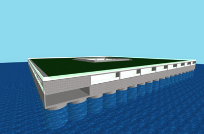
[this is actually one of a series of designs I have worked on for a near-shore
marine condominium serving as a seed for a marine colony. This structure
would be similar in basic composition but would use larger scale PSP cells]
As the facility expands it would assume a more radial structure with a
larger number of decks formed of higher storey bays surrounding a deeper
well, perhaps taking a form similar to this;
At this stage the facility would begin hosting permanent staff, individual
bays on the perimeter providing apartment space and certain decks becoming
dedicated to community services like medical, recreation, and shopping.
The chief business role of the SE venture is leased facilities with leased
space on orbit complimented by corresponding support facilities on the Downstation.
In this way the Downstation would grow into a large permanent community
hosting the workers of these leased facilities and of the community services
that support them.
At a certain scale a community PRT (personal rapid transit system) running
within the deeper interior portions of the structure would be added. This
transportation system functions as a kind of elevator traveling horizontally
and vertically and using different function cabs for different jobs, some
to move people, others to move cargo up to the size of a marine shipping
container. This system would evolve from a marine container conveyor system
used inside the early structure for managing container storage and for moving
payloads and equipment to the tether terminus well. This PRT system would
also function as a PPT (personal packet transport system) using a robotic
cab to collect and convey smaller meter-sized containers door-to-door. It
would be like having a dumb-waiter than can go door-to-door throughout the
facility and would see significant use in integrating industrial systems
located in different points in the Downstation. The PRT/PPT would eventually
be integrated with the full scale space elevator car system allowing for
tight integration between on-orbit factory facilities and factories on the
Downstation. It would also have the benefit of giving Downstation residents
door-to-door transportation to space.
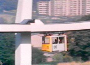
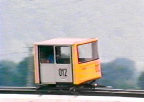
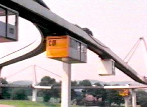
[PRT system with alternate supported/suspended drive and mult-size multi-function
cabs. circa late 1960s]
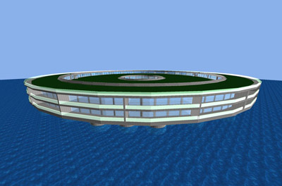
As it grows in area the Downstation would also climb upward around the
tether well, absorbing the earlier tether support tower enclosure, and assume
a concentrically terraced form. While open deck space near the center would
still be dedicated chiefly to the SE systems use, the lower outer areas would
tend to be dedicated to diversified industrial uses and intermediate terraces
would increasingly be given over to the use of public gardens and cold-bed
farming. This would give residences in each terrace-perimeter a more suburban
aspect, the emerging megastructure assuming the overall aspect of a mountain
sloping upward to meet the SE tether. The perimeter of this structure would
feature small round bays for small boats and recreation, large pie-segment
ports for commercial shipping, and clusters of pens for aquaculture exploiting
the deep-sea discharge from the downstation's deep sea water AC system.
[note: those aren't flying saucers. They're lenticular airships]
A satellite platform located some distance away -cheifly for noise abatement
reasons- would function as a commercial airstrip. Using its massive flight
decks as gigantic thermal collectors, the airstrips could double as a solar
dynamic power plant, adding to the potential power output of the facility.
Below-deck space would serve as airport facilities and a vast air cargo
terminal. It may look similar to this floating airport design from Float
Inc.;
This airstrip facility could evolve from what was initially a hybrid airship/rocket
or conventional rocket launch facility built to provide a base of vehicle
assembly and launch nearby the Downstation facility. Such a facility would
be similar to the initial Downstation structure but instead of evolving
to a radial form it would remain square, eventually sprouting airstrips
from two opposing sides. As a launch facility it would use either a vast
tension structure hangar covering its area or it would feature a large NASA
VAB-like tension structure which rides on tracks to enclose a self-mobile
floating launch pad when docked to the platform, allowing a large rocket
to be assembled on the launch pad which then moves whole to launch position.
Such a local launch facility is not strictly necessary for the initial tether
deployment but could be justified in the context of its planned evolution
to an airport when the SE obsolesces rockets in its construction plan.
Operational Scenarios:
Pre-deployment scenario:
The SE program begins with the development and testing of its initial tether
systems components. This would also be relied on for generating the media
attention required to attract investment in the initial tether deployment.
Several technology demonstrations would be key to drawing attention to the
project;
Telerobotics demonstrators: Since the small scale of the initial tether
limits most initial on-orbit activities to what can be done by telerobits,
it fall to the SE venture to demonstrate the viability of telerobotics technology
for this. This would involve the prototyping and demonstration of several
types of telerobot systems; climbers, climber laminators, on-orbit service
robots, and self-contained robot lab modules. These systems don't need to
be put in space to demonstrate their use. They simply need to demonstrate
their remotely controlled operation at a convincingly long distance and
give potential clients a feel for how operations on the Upstation would
be conducted -and inspiration for their own project ideas. The systems would,
however, be later demonstrated on the aerostat demonstrator noted below.
Hybrid airship assisted launch demonstrator: Balloon assisted sub-orbital
launches have already been well demonstrated but in a vertical vehicle orientation
with conventional sounding rockets. This project would demonstrate an initial
horizontal aligned guided dirigible assisted launch to LEO of an open space
frame payload. Smaller in scale than the full scale tether carrier system,
it would be based on the same modular components for the dirigible and tether
carrier structure, the truss using conventional rigid struts, the dirigible
using pneumatic struts. Recovery of the dirigible hull would allow its components
to be re-used in the later larger launch system. The demonstration truss
payload would function as a chassis for an academic science package or some
simple communications satellite or it could be simply sacrificed after successful
launch.
Dirigible aerostat tether demonstrator platform: This project uses essentially
the same dirigible hull system used in the hybrid launch system as the basis
of a stratospheric aerostat which supports a full-scale prototype of the
tether carrier truss. Flexcells on the dirigible hull provide power to stationkeeping
systems based on plasma thrusters, as used in telecom aerostats. This functional
mock-up tether carrier carries a short length of the same type of tether
planned for orbital deployment as well as the prototype for the 'down' terminus
instrument capsule. It would be used to test and demonstrate tether deployment,
capture, and anchoring. It would also be used as a test-bed for tether climbers,
Upstation telerobots, and power/communications systems. Development cost
recovery for this demonstrator would be achieved by its conversion into a
telecommunications aerostat which would be used to provide wireless broadband
services, as well as hosting atmospheric research systems. This itself is
potentially extremely lucrative and could be exploited as a bootstrapping
venture to finance the rest of the initial tether deployment program. This
would establish the SE venture as a revenue generating venture even BEFORE
the SE itself is deployed. A very powerful credibility booster.
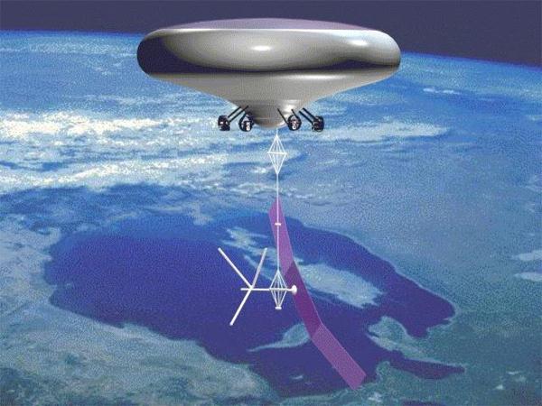
[LTAS telecom aerostat platform]
Downstation platform demonstrator: This would, essentially, be the ACTUAL
initial Downstation structure. It would be built to provide the SE venture
with a tangible showcase facility featuring equipment mock-ups and could
serve as functional downstation and launch facility for the aerostat demonstrator
and hybrid rocket demonstrator. However, it would also serve very well as
a fully mobile corporate HQ, workshop, and lab facility for the SE venture
and would retain its value by being potentially resalable for off-shore
residential, industrial, or research applications. It is a mobile piece
of real estate and could be located in and later moved (move itself!) to
just about anywhere in the world. It can also recover its development cost
through the aerostat demonstrator's re-use as a telecom platform, since
it would function as its telecom downstation, and by leasing space for marine
and meteorological research facilities.
Initial deployment scenario:
Deployment begins with the launch of the initial tether carrier truss package,
either by conventional or hybrid rocket. Upon reaching GEO, the truss package
would align itself vertically, deploy its solar panels and communications
systems, and begin its uncoiling of tether from both ends. The steerable
'down' module should eliminate the problem of finding and recovering the
end of the tether as it is lowered since it would be in constant communication
with the launch control center and could be 'flown' by remote control toward
the mid-ocean Downstation.
Capture would be performed by lofting an intercept cable on moored balloons
several miles apart, similar to the capture cables deployed in the old early
20th century air mail system. This might require some protective sheathing
of the lower end of the tether to reduce damage from cable friction. The
capture cable would also double as the grounding strap for the tether. Weather
should be a minimal problem for this process because the equator is subject
to little weather, hence its maritime reputation as 'the doldrums'.
Upon capture, the tether would be towed by boat to the Downstation platform
and installed in its anchor receptical, held in place by magnets or roller-bearing
clamps with a motion compensating slack spool rig or perhaps a system of
attached dynamic ballast tanks below the water line. First order of business
after the initial tether deployment is using climbers equipped with sensing
equipment to analyze the tether integrity and test the performance of the
climbers in all conditions along the tether length. Then tether expansion
begins, alternating with payload transfers to the Upstation. It is likely
that the SE venture would go to deployment with a fairly full schedule of
Upstation and Downstation lease space clients, though these initial clients
will not be for permanent facilities due to the small scale of initial Upstation
facilities. On-orbit launch service clients would tend to come much later,
as the payload capacity of the climbers grows to allow more useful vehicle
packages.
Initial operational scenario:
Key to making this whole SE vision work is continuous revenue generation
from the tether in all stages of its construction. It MUST be able to turn
a profit from the moment the initial small tether is deployed, if not before.
It is likely that upon deployment many potential clients will line up seeking
space at the Upstation for different projects along with corresponding Downstation
support space. And, of course, there will be many people wanting to launch
satellites and other vehicles from the Upstation and higher points on the
tether. But since human habitation on-orbit and on-tether would be unlikely
for some time due to the small unit payload capacity of the rudimentary
tether(s), activities in space would be limited to what can be implemented
with small systems via telerobotics -still a very significant amount and
diversity of activity but limited in scale. Thus I see the initial operational
model for the SE being essentially the same as that of the MUOL, as noted
earlier in the Upstation design section, with that addition of space transport.
Being limited to a relatively small climber payload capacity, the small
module scale of the MUOL makes perfect sense.
The basic premise here is that the Upstation structure presents a kind
of 'real estate' which is organized into lease space units according to
its modular geometry and the form factor of unit modules which plug into
it. The SE venture's job is akin to that of the management of a large commercial
office building; building and maintaining unit space which lease clients
use as they wish within the practical limits of safety and available infrastructure
services. The vertical orientation of the initial truss relative to the Earth
is less well suited to this than the horizontal planar space frame of the
MUOL because many applications -particularly telecommunications ones- require
an unobstructed terrestrial view. Telecommunications being the most likely
initial adopters of space on the Upstation, its first order of business would
be to construct a perpendicular plane space frame around the core truss -as
described previously- in order to mount this type of equipment. This would
take the form of first a simple boom which is widened until it completely
surrounds the core truss.
After telecommunications, the next area of in-space business would be industrial
research, the structure providing plug-in space for automated modular lab
units. These would take the form of temporary labs, removed whole after
completion of their work and either discarded or returned to Earth, or permanent
labs, which are periodically serviced with their own plug-in modules in
order to restock them with supplies or to remove process samples. This phase
of use is critical to the future of the SE and the future of space development
in general since space will only see sustainable investment when a robust
assortment of products valuable on Earth can/must be manufactured in space.
Like any space program, the SE faces the challenge of inventing reasons
for its existence. This is why orbital industrial research is critical.
(why that hasn't always been obvious to people in NASA is beyond me. There
is no more important 'mission' for the future of the space program than
in-space industrial research)
Logically enough, the next development phase would be the implementation
of on-orbit factories, some of which would be operated by the SE venture
itself in order to fabricate tether material on-orbit for its expansion.
We can't precisely predict what products are likely to emerge out of the
orbital industrial research but likely areas will be in photonics, microelectronics,
drug synthesis, bio-engineering, and nanofabrication exploiting the vacuum
and microgravity. First generation factory modules will be similar to first
generation lab modules, designed as small fully self contained packages which
are brought to the Upstation whole and brought back when they are depleted
of materials. Second generation systems would use plug-in casettes for input
and output. Later units will split into separate plant and transport modules,
then into multi-module production lines where different workstation modules
are linked together through module access ports. The likely architecture
of these factory systems would be simple, building upon the architecture
of lab modules. Process hardware consisting of plug-in modules are arranged
radially around a central open space, each plugging into a radial backplane
like computer boards and accessed by a set of simple telerobots operating
on a track shaft running through the module center. A telescoping extension
of the track shaft allows the robots access these add-on compartments while
side-to-side ports allow robots in one module to hand off items to those
in adjacent modules. Following this design strategy, factories of most any
scale would be possible, with the bulk of the products limited by the size
of the unit modules.
Since the first generation of lease clients would be running telecom systems
and labs, the companion Downstation facilities they would lease space for
would be primarily control centers and small service workshops. This would
be further supplemented by non-space facilities in the form of marine and
meteorological research facilities. So right away we could see a sizeable
contingent at the Downstation, even though it would be a relatively compact
facility. However, this would increase in proportion to the payload capacity
of the climbers/elevators and the transition to on-orbit manufacture, becoming
comparable with any conventional light industrial facilities by the time
the first full scale elevator system is installed. Eventually the Downstation
would be hosting all the product processing that can be done on the ground
around materials or subcomponents made in space, outputting a finished packaged
product for export.
As for the SE's use as a launch platform, this capability would tend to
be initially limited to small very small self-contained spacecraft which use
ion/plasma propulsion and/or solar sails and tether spools for propulsion.
In essence, microsatellites. Launch would be based on climber transport
to the Upstation and then release via the Upstation's own robot arms or
by a robot on a climber which travels to points above GEO on the tether
length, exploiting the centripetal force to send vehicles to other points
on GEO and to escape trajectories. However, by employing the same component
architecture used by the Upstation structure itself it becomes possible
to overcome the payload limits of the early thin tether by assembling modular
spacecraft on-orbit. Vehicles of any size would be possible, including manned
spacecraft based on transhab habitat components -this even before the tether
itself can support human passenger traffic. This offers a whole new service
area for the SE venture; manufacture of spacecraft on demand from modular
components. This would require both dedicated assembly 'creche' space on
the Upstation and manufacturing facilities on the Downstation. The most likely
initial uses for this capability would be the construction of very large
telecommunications platforms intended for other GEO locations, followed
by solar power satellites, prototype solar sail spacecraft, as well as interplanetary
research vehicles.
Initial operations at the Downstation would rely heavily on Sri Lanka or
the Maldives as a point of relay, for supplies, workers, and communications.
All equipment for use in space will be manufactured elsewhere -primarily
in North America, Europe, Russia, and Japan- and sent to the site, through
air ports and ports in Sri Lanka or the Maldives. Local facilities could
be robust, but most initial workers will still work in shifts akin to that
of oil rig operations and that means coping with a high transportation overhead
and a high salary because of the inconvenience these works must deal with.
This points out a key issue.
The most critical logistical issue for the SE venture is, ironically, transportation
to the Downstation from and to the rest of the globe. The Downstation is
still going to be at a relatively remote location; 400-600 miles from either
the Maldives or Sri Lanka. This is beyond the typical range for helicopters,
which are not cost effective in any case, and while the structure itself
could readily support container ship service, the SE venture will not be
big enough to be put on container ship routes for a while. It will also be
too small to host an airstrip large enough for commercial air liners. An
airstrip capable of supporting commercial airliners would be about 2700-3000
meters by 100 meters and would cost in the area of $2.5-$3 billion dollars
based on PSP construction. (that's conservative. For a mid-ocean airstrip
supporting aircraft on par with the 747 airlines could demand a length of
3500m and twice the width. An Atonov heavy cargo aircraft requires a basic
3500m runway) That would likely have to wait for a while, unless it was already
built as part of a pre-deployment marine launch facility which was paying
for it through operation as a commercial launch facility.
This presents a real problem because current transportation technology
offers no low cost, intermediate scale, long range transportation options.
Thus the SE venture is initially forced to relay from these two nearest coasts
and must bear the cost of its own relay transportation. There are three classes
of vehicles readily available that offer the most likely choice for this;
First is the oil industry type 150-300 foot PSVs (platform supply vessel),
mini-supply vessels, or FSVs (fast supply vessels) capable of carrying several
shipping containers, palletized cargo, and 50-70 passengers. All these vessels
are similar in form, with slight variations in engine power, flat deck area,
and interior passenger accommodations. But they only manage about 25-30
knots, have very limited range, and cost in the area of several million
dollars each, new. 1000 miles may be their range limit.
Next is intermediate sized RoRo (roll on roll off) container/cargo ships.
Typically used for secondary shipping and ferry service for island communities,
these are 250-400 feet in length and can be purchased used for between $2-10
million dollars -$10-15 million new- have a capacity of about 100-150 20'
containers, and manage about 15 knots. This is a pretty good class of vessel
for the Downstation's needs when coupled with the side-docking capability
of the PSP because these vessels are multi-function, offering container,
vehicle, and pallet handling with Roll-On-Roll-Off handling via on-board
ramp systems. They may also have much longer range than PSVs. But their
very slow speed is a bit of a problem for use in longer range transport.
They would put the Downstation at around 40 hours from the Maldives or Sri
Lanka. There is a possibility that lease service of these intermediate class
vessels is possible from Sri Lanka as it is likely to be hosting that service
for the benefit of the Maldives. If this can be determined, it would make
the initial transportation logistics more streightforward but may not be
comfortable for routine passenger transport. If the vessels were owned,
this could be readily overcome by converting a certain portion of container
space to passenger cabins using adapted shipping containers.
The next most likely option is the so called 'fast ferry' class of vessels.
These are typified by multi-hull vessels in the 100'-125' range used mostly
for inter-island, large bay area, and intercoastal transport. They offer
relatively high speeds in the area of 40 knots but with high fuel consumption
and cost in the area of $20-40 million dollars new, around $15 million used.
This class of vehicles would put the Maldives and Sri Lanka at 10-15 hours
away. SWATH (small water area twin hull) offer the best performance and fuel
efficiency with the most stable ride but remain rare and expensive. Designed
mostly for passenger service, fast ferries offer high passenger capacities
up to a few hundred people but with accommodations designed for short range
ferry service and fuel tanking limited to short ranges. However, their catamaran
hulls and clear-span superstructures make them easy to adapt, thus allowing
ready refitting or customizing to support long range multi-function use.
Likely configurations would offer passenger capacities in the area of 30-50
passengers and palletized cargo handling but no container handling, due to
the typically light aluminum deck structure. This adaptation would add about
a third to the vessel cost. These might be a better choice as a specialized
passenger vehicle rather than a mixed use vehicle. New marine capable RoRo
fast-ships with mixed-use intermediate cargo capacity are starting to appear
but remain too new to be found used.
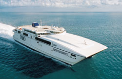
[recently developed fast-ship RoRo mixed use cargo and passenger vessel
operating out of Australia. 41knot cruising speed]
Long term, the SE venture needs to free itself from relying solely on Sri
Lanka and the Maldives as waypoints in order to support consistent growth,
possibly sooner than its scale will justify more conventional transport
options. So more unconventional transport may need to be explored.
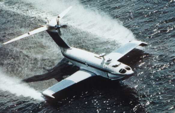
Sea planes are no solution because ones large enough to land and take off
in the open sea no longer exist. However, there is one similar vehicle which
may offer this capability; the Orlyonok Ekranoplane, made by Volga Shipyards.
Marketed as a kind of fast ferry, this is the closest thing we have today
to a jet airliner that can land on the open sea, though technically it's
a surface effect vehicle that never gets above 50' altitude. The Ekranoplane
is a very efficient vehicle, offering high speeds but at less fuel consumption
per flight hour than conventional aircraft of comperable size and speed.
It uses three engines; two nose mounted jet engines and one tail mounted
turboprop. In flight only the turboprop is used, the nose jets only providing
take-off assistance. It costs about $40 million, has an operating cost of
about $5000 per flight hour, has a capacity of 250 passengers or 180 metric
tons of cargo, has a cruising speed of 430kph, can land and take off in 2
meter (category 5) seas, and would have the range to reach everything from
East Africa to Malaysia in a single hop. But it's still a pretty expensive
vehicle. One version of this vehicle was designed for nose-seperation loading
(it's original role was as a very high speed long range landing craft) which
would be fine for palletized cargo but it is not clear if it can accommodate
marine containers. Air cargo containers should be readily supported.
Using the technology employed in a hybrid launch system, it is possible
the SE venture could solve its transportation dilemma by adapting the launch
vehicle hull technology to use as a general transport dirigible airship.
Such vehicles would be similar to or the same as the vehicles proposed by
the LTAS corporation [ http://www.lvcm.com/walden/
] using hybrid propulsion based on a combination of flex-cell PV sourced
solar power and a compact turbogenerator or fuel cell. Traveling on fuel,
they would have a range equivalent to the Orlyonok but a cruising speed of
about 150mph. On solar power alone these vehicles would have an unlimited
range at a cruising speed of about 60mph. They could operate in either mode
on demand. They offer the lowest operating cost of all forms of air -or sea-
transportation, regardless of which operating mode is used. The old technology
Hindenburg could travel from NY to LA on less fuel than a 747 consumes taxing
on the runway. Using the same materials as the SE tether itself, this performance
could be increased much further by virtue of a much lighter, stronger, and
thinner shaped hull system. Hangar facilities are unecessary for lenticular
hull airships because their cross-wind susceptibility is much lower and, relying
on the control technology used for the hybrid launch system, vehicles can
be simply parked in the stratosphere when not in use. Such vehicles have a
distinct advantage in that the SE venture could manufacture them itself while
their VTOL capability makes it easy to service the Downstation and reach
deep inland areas. It is both practical transport and a valuable product.
This makes synergistic use of the fabrication capability the venture must
develop for a hybrid launch vehicle, aerostat demonstrator, and for climbers
and elevators.
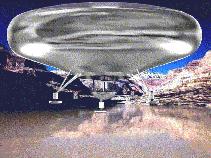
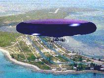
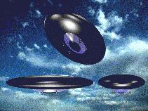
[three sizes of lenticular airship. Pictures from LTAS]
Much of this transport problem could be alleviated by reducing the need
to use workers in shifts as with oil rig operations, instead equipping the
Downstation to allow them and their families to live comfortably on the Downstation
itself for indefinite periods. The greater the self-sufficiency of the Downstation,
the more community-like its aspect, the lower the rate of worker rotation,
the lower the dependency on Sri Lanka and the Maldives for worker accommodations,
the less critical high speed passenger transport becomes, and hence the
lower the operational transport overhead. The more permanent residents the
Downstation can host the more net transport volume for the complex, the
sooner it can get container ship line recognition and the sooner it can
cover the costs of a commercial airstrip. So the logistics of Downstation
operation favor its evolution into a full-blown city or marine colony.
Later operational scenario:
As we've already established, revenue streams for the SE venture -that
is to say the sources of income- would be both ground and orbit based with
the essential role of the SE venture being that of a leased space and space
transport service provider which provides space -on-orbit, on-tether, and
on the Downstation- for different industrial and commercial activities and,
of course, the transportation and communications linking them. It's important
to recognize that the Downstation structure -as the closest point of space
access- is just as valuable a commercial asset as anything in space -in
fact, potentially more so because the volume of Downstation space demand
will grow faster than the Upstation space demand.
The reason for this is that, even though the SE itself drastically reduces
transportation costs to space, doing things in space will still be more
expensive than doing things on the ground due to the rigors of the environment
facilities must deal with there. Even if it cost you nothing to travel to
and from Antarctica, a factory built there would always be much more expensive
than the same sized facility in California because it must tolerate a vastly
more harsh environment and so is inherently more expensive to build and
operate. So in the event of a robust Upstation industrial facility, it's
matching Downstation facilities may be many times larger because companies
will only put what absolutely must be put in space and leave the rest on
the ground nearest the point of access to space. Why put all this factory
space on the Downstation rather than in Sri Lanka? Initially, much of it
may be put there. But the site of the Downstation is still remote enough
that the transportation overhead between Sri Lanka -or from there to anywhere
else on the globe for that matter- and the Downstation would be high and
result in much production delay. This would be true even after the Downstation
can host container ships and full size airliners. So in the long run economics
favors complete production to a finished packaged product at the Downstation
for direct transport to their markets aorund the globe.
Here then is the driving force that turns the Downstation into a large
self-supporting community -a full-blown marine colony. All this activity
would require a fairly large worker base but cycling them between the Downstation
and its nearest neighbors is more expensive than having them live continuously
on the Downstation. It also presents a certain hardship to workers to be
seperated from family for extended periods -one reason for their higher salaries.
Thus it becomes more economical for the Downstation itself to host facilities
not only for workers but their families as well, and thus you have the makings
of a complete community as community support services -shops, restaurants,
schools, clinics, recreation, personal transportation, personal financial
services, agriculture- follow on the heels of these families. Initially all
food and supplies would be imported to the Downstation but, again, this is
more expensive then producing them locally if possible. Using deep sea water
for AC and industrial cooling, the Downstation has a very useful agricultural
resource. This artificial upwelling would provide the basis of polyspecies
mariculture using simple floating pens and frames attached to the perimeter
of the Downstation platform and algaeculture solar frames on the roofs/terraces.
The cold water also enables the use of cold-bed farming which allows the
creation of compact farms supporting temperate climate crops. Algaeculture
and mariculture would provide a source of nutrients for hydroponics, supporting
this rooftop farming. Carry this out to its logical conclusion and you get
the makings of a complete self-supporting community. This is why it's so
important for the Downstation structure to be so freely expandable.
While leased space and space transport would be the SE venture's primary
areas of business, a number of other industries would be critical enough
to the SE development project itself that the venture would most likely need
to implement them. One is telecommunications, primarily between the downstation
and the upstations but also between points throughout the wireless telecom
'footprint' of the GEO upstation. With submarine cable link to Sri Lanka
and India, this becomes a powerful source of revenue in and of itself, the
SE capable of providing freely expandable wireless telecom services (phone,
TV, Internet) across much of Asia and Africa.
Next is electric power. The tether itself is a potential source of power
as an electrodynamic generator. In addition, the GEO upstation would serve
as a good solar power satellite platform and a nexus for multiple SPSs,
communicating their power to the upstation by laser or microwave link. There
are many ways for the tether to communicate power to the downstation. If
it's designed as an electrodynamic system, it is already delivering its power
to the surface and the downstation need only 'plug in' to the tether. However,
the great length of the tether may present so much net resistance that,
being a DC system, only by equipping it with a superconducting cable could
its full power potential be tapped. Otherwise, it could serve as a simple
coaxial cable for power sent via high frequency modulation or in the form
of microwaves to the surface. However, the long distance could still mean
unacceptable power losses with conventional conductors and so the tether
might use another means of conveyance with a higher current density.
One possibility is to use a hollow evacuated duct in the tether as an optical
guide for laser energy transmitted down it. This would be converted to electric
power by an array of actively cooled photovoltaic cells optimized just for
the frequency of the laser light. PVs are extremely efficient at individual
frequencies. A collector a few meters in size could convert gigawatts of
power. Potentially vast areas of PV collectors could be arrayed on the tether
by lining the optical cavity with them and inserting a conic reflector through
the center. The problem with general PV solar cells is that it's difficult
to make PVs equally responsive to all frequencies of light and this translates
into much reduced efficiency. But tailored to one or a few frequencies,
they easily reach 90% and greater efficiency. This has already been exploited
to provide electric power to in-line devices on long fiber optic cables.
After it's own local consumption, India would be the primary market for
the power from the SE, the country being potentially within range of the newer
longer range submarine power cable systems -and using Sri Lanka as a bridge.
Since there is no actual global power grid, marketing power elsewhere would
require packaging it in a ship-transportable form. This could be accomplished
by production of hydrogen, solid sodium hydride, liquid borohydride, or
charging of vanadium sulfate redox solution. These latter three mediums
are the more practical in that they offer the highest energy storage density
and highest safety. In fact, they are generally safer than fossil fuels.
The hydrides are used as fuel in reaction with water producing hydrogen
on-demand to a fuel cell or turbogenerator. Solid sodium hydride must be
encapsulated to preclude runaway reaction while for liquid borohydride this
presents no problem. The redox solution uses a redox cell, a kind of 'battery'
that uses liquid electrolytes in bulk storage tanks which are pumped through
a proton exchange membrane stack for charging or discharging. In all these
cases the packaging medium needs to be returned and recycled to be reused
which presents a certain overhead. But considering the overhead in conventional
refinery, the specialized storage and transport hardware, and the ilicit
government subsidies fossil fuels require the costs break even and the end
result is a competitively priced pollution free source of energy which, while
not suitable as a replacement for all fuels, is immediately suitable for
all stationary and large vehicle portable power systems. Currently most
stationary and large vehicle power systems are based on turbines with stationary
fuel cell system use growing at a rate of at least 100,000 units per year
-not counting the newly introduced residential fuel cells.
Having solar power satellites, constructed on and maintained from the GEO
Upstation, directly beam power to local markets via microwave is also a
practical approach but it suffers from a need for multiple rectenna facilities
which, because of their large scale and type of technology, suffer the same
problem of delivering energy to their nearby markets. SPS rectenna arrays
would be vast, albeit simple, structures which, because of the need for
large areas of contiguous real estate and the inevitable NIMBYism that plagues
projects of this nature, must be relegated to very remote locations, thus
recreating the same problem of linking the power source to the grid that
all large scale renewable energy projects have struggled with.
The largest cost of any power utility is not in the power production systems
but in the systems of power distribution. The real obstacle for renewable
energy has not been in making power cheaply but in delivering it to the
grid cheaply, since in most cases the best places for things like solar
and wind power are places far removed from the urban areas where the greatest
power demand is. (this is why Canada's vast hydroelectric potential isn't
powering the whole American continent and why Iceland isn't powering all
of Europe with its geothermal energy)
The remote rectenna array faces the same problem and so it could end up
having to resort to an energy packaging medium to overcome the extreme up-front
expense of cabling to the urban market. In that case, it would make more
sense to centralize the packaging of this energy on a small number of plants
at strategically located points best suited to efficient transport. Equatorially
located marine rectenna arrays would probably be the easiest to construct,
from a bureaucratic red-tape standpoint, and could be built at the SE Downstation
from the same structural systems used by the Downsation. The vast area of
the PSP structures makes it easy to incorporate on-board power packaging
plants and shipping terminals as well as vast hydroponics farms, local worker
housing, and any number of different industrial facilities. (there would
be virtually no microwave leakage below the rectenna grid, and any of that
would be readily blocked by the concrete of the platform itself)
The third critical industry is carbon and tether fiber production. While
initial tether fabrication could rely on any available source of material,
as the SE project progressed it would soon become the Earth's single largest
consumer of industrial carbon. Where does this come from? The closer the
source of material to its point of use the cheaper it is. So eventually the
SE venture would be compelled to implements its own carbon production and
tether fiber fabrication as close to the SE as possible. Many SE plans have
proposed the exploitation of carbonaceous chondrite asteroids as a source
of carbon. But this presumes the pre-existence of an on-orbit industrial
infrastructure capable of sending mining vehicles to asteroids and returning
their raw materials for on-orbit refinery and fabrication or the transport
of whole asteroids to GEO. But at this point in time this presents a chicken-or-egg
dilemma. We are looking to the SE to enable that orbital industrial infrastructure,
so how can its construction depend on it? Thus the more practical source
for this carbon may be the Earth's own atmosphere. Our industries have, since
the advent of industrialization, dumped so much excess carbon into the atmosphere
that there is enough there to build hundreds of SEs. But how do we extract
it? It would be great if we could get people to collect the waste CO and
CO2 from all their primitive internal combustion engines, bottle it, and
ship it to the SE but that's not realistic. We need to, ideally, get it from
where we dump it; the atmosphere. This would not only meet our material volume
needs but also make building the SE of direct benefit to the global environment.
Nanotechnology advocates have envisioned the creation of artificial trees
which use nanomechanisms in the surface of their 'leaves' to collect carbon
molecules from the ambient air. But using a less advanced technology, much
the same thing can be done in a couple of other ways. One would be fractional
distilation of cryo-cooled air. This is a process similar to that used to
refine fossil fuels except that one is using liquified air and tapping off
select gasses from it along a gas column. This is an already common industrial
process -used chiefly for liquid nitrogen and oxugen production- and would
be used to extract carbon dioxide which would be catalytically reduced to
carbon monoxide used as the feedstock for nanofiber fabricators. But this
is a pretty energy intensive approach. Another lower energy approach would
be to employ solar energy and natural 'nanomachines' in the form of algae.
One would mass culture algae on the Downstation using arrays of culturing
frames or trenches then incinerate the algae in a closed environment to
produce carbon monoxide. This has the side benefit of producing a potential
food product as well, both for direct human consumption and also as a feed
stock for polyspecies mariculture. The same technology could also be employed
to culture algae in an anerobic phase in order to produce hydrogen. Another
benefit could come from culturing lithophoric algae which could, when incinerated,
produce slaked lime and silicate sand to be used in the concrete construction
of the Downstation complex itself, and any PSP structures it makes for export.
Combining this with nanofiber as a homogenous cement reinforcement and thus
eliminating steel reinforcement, the Downstation could become completely
self-sufficient in production of its own structural materials, as well as
structural materials used on the Upstation.
The fourth critical industry would be manufacturing of modular components,
robots, and other systems for the SE Upstations. This is pretty streightforward
light industry assuming space frame based construction as decribed previously.
Initially, this work could be done anywhere but later it can economize by
Downstation location just as other industries do, exploiting the local nanofiber
production capability as a source of material for composite components and
possibly using production capabilities of the local industrial clients in
a symbiotic fashion. A great many of the materials and components used on
the Upstation have potential use on the Downstation. Truss components used
for the Upstation can be used for interior deck joists and furniture parts
in the Downstation homes and offices, robot technology made for space can
also be used in Downstation plants, dirigible hulls used in hybrid launch
systems lofting Upstation components can be used to create general transport
VTOL airships serving passenger and cargo uses for the Downstation. Many
synergies are possible.
The fifth critical local industry would be food production, initially for
Downstation consumption as noted above, then Upstation consumption, global
market, and eventually for an interplanetary market. Combined with the rich
mix of food products imported to the Downstation from elsewhere, this offers
a unique international mix of cuisine for the Downstation residents, and
potentially very exotic menus for the eventual tourist facilities on the
Upstations. Indeed, with the SE as a potential key supplier of food for manned
outposts throughout the solar system, we can expect future astronaut menus
to be likewise diverse; a rich mix of Asian spices, tropical fruits, a broad
spectrum of seafood, and high-tech food chemistry and packaging.
The sixth critical industry is tourism, though this may not be as critical
as many space advocates today suggest. A lot of space development schemes
put much stock in the power of tourism. I do not think it is all that sustainable
since the the experience of space is difficult to differentiate from one
facility to another, does not lend itself to a sliding scale of accommodations
due to the high infrastructure cost, nor would living in space be anywhere
near as romantic as expectations suggest. (It's sub duty with a nice window
view, people! It only gets better the more 'outside' you can simulate inside.)
So it is likely that the first space tourism venture in Earth orbit may be
the only one. It's sort of like having one beach to share among any number
of hotels. How do those hotels differentiate the beach experience in such
a way as to secure market share? The SE, however, does offer a potentially
very low transport cost and this means that on-orbit facilities have a lot
more room to differentiate the quality of the experience -even if it comes
down to room size and a difference between a Star Trek Next Generation style
of luxury decor and an ISS style of budget decor. But much of the 'thrill'
of the space experience is really about riding a rocket, which is something
the SE eliminates. So in essence it will tend to be sort of like a hotel
sitting on top of a really tall CN Tower with the novelty of a zero-g playroom
added in. And, ironically, by the time the SE is able to carry routine passenger
traffic, tourism may be the ONLY commercial application with any practical
need for humans.
The tourism potential of the Downstation, however, should not be overlooked,
especially when it has achieved a significant scale with a robust local
community. The Downstation could offer its own very unique twist on the
theme of the tropical ocean resort. It would offer a very unique urban environment,
free of automobiles and their pollution, homes and other buildings covered
in carefully tended rooftop gardens, a unique local quisine, and a very pragmatic
space-focused culture. Even though it would start with a very westernized
atmosphere, it could not avoid the cultural influence of its nearest Asian
and Oceanic neighbors. I suspect it will eventually have much the character
of a cross between Singapore and Cape Carnaveral.
In summation, the ultimate vision of the SE is that of a fairly large city
in the sea connected by a kind of umbilical-like bridge to a predominantly
industrial city in space. Both Upstation and Downstation would function
in tandem as an intermodal communication nexus, linking the transportation
of terrestrial sea and air to the space transport linking destinations around
the solar system. In this respect both stations would have the aspect of
urban seaports, points of converging vehicle traffic. Whether or not the
Upstation becomes host to a permanent community of residents like the Downstation
is hard to say. Humans may always be less cost effective to host in space
purely as a worker base. So the issue is likely to come down to how compelling
space is as a residence regardless of its economic practicality. I suspect
this will require technologies enabling very large amounts of habitat space,
basically because living in space is about living indoors 99.99% of the time.
GEO especially is not going to be a place where 'space walks' are normal
by any means. This may mean that viable permanent human settlement of the
Upstation may be contigent upon creating vast centrifugal artificial gravity
habitats around the tether capable of providing at least the same quality
of life found on the Downstation. But we can leave such speculation to another
time. For now, these scenarios adequately cover the potential 20-30 year
future of an SE venture.
Eric Hunting - 8/11/02


