
LED Installation instructions, discussion, troubleshooting and tips
Thank you for your recent purchase!
In order to better serve our customers, we have put together this special page of installation information. We hope this will help make the installation go smoother.
Automotive wiring circuits are much more complex than you might think.
R E A D T H I S F I R S T :
It is very important that you only remove and replace one bulb at a time. Do not remove/replace additional bulbs until the first bulb is working properly. A missing or improperly installed bulb can effect other bulbs in remote locations of the vehicle and this can become very confusing.....very quickly.
General
Our bulbs are all tested prior to shipment. If your led is not lighting at all, chances are that the polarity is reversed, proper electrical contact is not being made in the socket, or the circuit is not getting electrical power (ie broken wire, blown fuse, etc..
All of the automotive leds that we sell can be powered directly with 6-15 volts of ac or dc power. A couple of wire leads connected directly to your battery or any 6-15 volt power source can be used to check and troubleshoot your bulbs. If the bulb does not light, reverse the polarity immediately. Although reversed polarity should not damage our bulbs for short durations (due to the special circuitry installed in each bulb), prolonged connection with improper polarity can cause permanent damage to the led.
You cannot connect these bulbs to higher voltage power sources such as household current. This will immediately destroy the led.
If installing multiple leds in a vehicle, always install only one led at a time. Many automotive circuits are quite complex and will react to changes such as missing bulbs, changes in resistance and bad connections in various ways. An improper installation in on one bulb can affect other bulbs in your car. If you start indiscriminatingly yanking bulbs out and putting in leds all over the car, without verifying proper installation and function, you will likely have many hours of aggravation trying to figure out what is going on.
Always follow these simple steps when changing out bulbs:
If possible, verify that the present bulb is working properly first.
Remove only one bulb from the vehicle.
Install the led.
Briefly test the circuit by applying power, (ie: turn on switch/ignition, apply brake, activate turn signal, etc…) If the led does not light immediately, cut power to the circuit immediately by turning off the switch/ignition, releasing the brake, switching off the turn signal, etc…)
With many leds (plastic wedge style and festoons style), the bulbs can be inserted 2 ways. If the bulb does not light, cut power immediately. Remove the bulb from the socket. Rotate the bulb 180 degrees and reinsert.
Proceed to removing/installing the next bulb only after the first bulb position is operating properly.
Terminology:
Polarity: Polarity refers to the +/- (positive and negative) side of a circuit. The electrical contact points on an led must be connected to the appropriate + or – side of the circuit or wire
Filament:
The small wire inside all incandescent light bulbs that glows when power is applied.
Incandescent bulb:
Any light bulb that used a glowing filament in order to produce light. If you look closely at an incandescent bulb, you can see the filament. If the filament is broken or a gap exists, the bulb is burned out and will not light. An incandescent bulb can be tested with an ohmmeter to determine is there is electrical continuity and resistance across the filament.
LED Bulb:
Light Emitting Diode bulbs use a special element that produces light as result of current flowing across two specially formulated elements. LED bulbs have no filament and the +/- side of the bulb are not connected. There is a gap between these +/- elements. This is why the led has no resistance and cannot be continuity tested with an ohmmeter. If you look closely at the led element, you can see the elements and the gap. This gap is normal and does not mean that the led is burned out.
1157
The 1157 bulb installation is quite simple, however there are a few issues you may encounter with 1157 leds.
The 1157 is a dual contact (d.c.) bulb. The dual contacts are connected to 2 separate circuits inside the bulb. One for bright (braking/turn signals) and one for dim (running/parking lights).
The 1157 led, like all leds, must have the proper polarity in order to light up in a DC (battery powered) circuit. The 1157 should have negative contact on the outer metal shell of the bulb and positive contact on one of the bottom contact points. All factory wired cars are already wired this way, but custom or modified circuits may be wired backwards since the polarity does not matter for an incandescent light to function.
You will notice that the 1157 has 2 pins on the sides. These pins are indexed so that the bulb can only be installed one way. Make sure you are inserting the bulb so that the lower indexed pin aligns with the corresponding lower slot in the socket. This will guarantee proper polarity unless the socket is wired improperly.
Once in awhile, factory circuits (or repaired vehicles) are wired improperly with the wrong polarity. This will result in the 1157 led not lighting. Before suspecting improper polarity, all other possibilities should be eliminated first. Polarity is best measured with a voltage meter, but if you are inventive there are many other ways to verify proper polarity in the 1157 socket.
1156
The 1156 bulb installation is quite simple, however there are a few issues you may encounter with 1156 leds.
The 1156 is a single contact (s.c.) bulb. The 1156 led, like all leds, must have the proper polarity in order to light up in a DC (battery powered) circuit. The 1156 should have negative contact on the outer metal shell of the bulb and positive contact on the bottom of the bulb. All factory wired cars are already wired this way, but custom or modified circuits may be wired backwards since the polarity does not matter for an incandescent light to function.
You will notice that the 1156 has 2 pins on the sides. These pins are non-indexed so that the bulb can be inserted either way. This bulb socket is designed to guarantee proper polarity unless the socket is wired improperly.
Once in awhile, factory circuits (or repaired vehicles) are wired improperly with the wrong polarity. This will result in the 1156 led not lighting. Before suspecting improper polarity, all other possibilities should be eliminated first. Polarity is best measured with a voltage meter, but if you are inventive there are many other ways to verify proper polarity in the 1156 socket.
Note: There are many 1157, 3157, and 7443 led (dual circuit) bulbs being sold that do not have diodes installed in them and /or have the diodes installed improperly. Without properly installed diodes, the dual circuit led bulbs will produce a bleed voltage across the unused circuit that can cause malfunction in many vehicles. All dual circuit led bulbs that we sell have the diodes properly installed to prevent these issues. This can be tested with a power supply and voltage meter. If you suspect that you may have purchased some dual circuit led bulbs from another supplier with this problem, you may email me for further instructions on how to test to see if this is the problem.
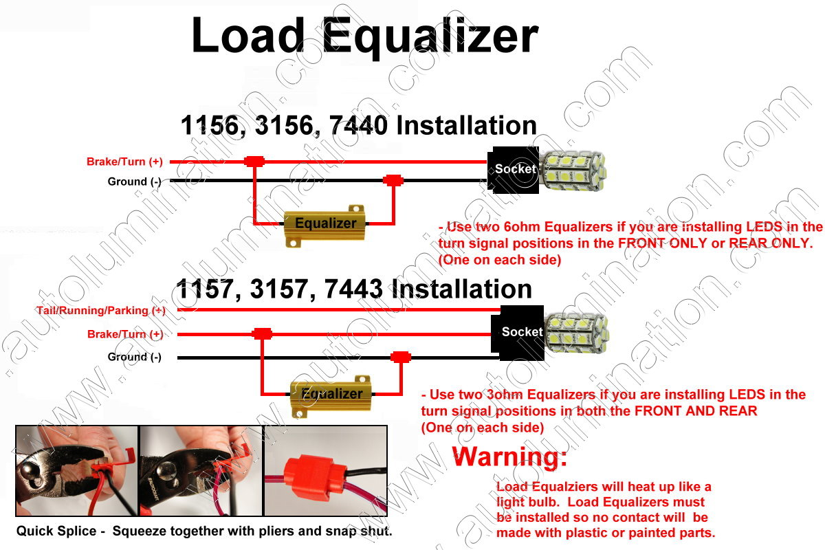
Turn Signal problems:
The 1157, 3157 and 7443 are often used in turn signal applications. Some vehicles have circuitry installed in their turn signal wiring that senses resistance across each turn signal bulb to determine if the bulb filament has burned out. These systems warn the driver of the burned out bulb by causing a rapid flashing of the turn signals, or in some circuits not flashing the turn signals and instead producing a steady-on condition.
This can be corrected by installing load resistors in each turn signal position where an led has been used to replace and incandescent bulb.
The load resistor simulates the resistance of the incandescent bulb and restores the turn signal to normal operating function with the led.
3157
The 3157 is the most complex automotive bulb and circuit to understand. The 3157 is a dual contact (d.c.) bulb. The dual contacts are connected to 2 separate circuits inside the bulb. One for bright (braking/turn signals) and one for dim (running/parking lights).
The 3157 has four separate wire contacts protruding from the bottom. If you examine the bulb closely, you can see that two of the wire contacts connect to the same point inside the bulb. These two contacts are the common negative (-) grounds.
The remaining two contacts are the positive (+) side of the circuit; bright (braking/turn signals) and dim (running/parking lights).
You will notice that the 3157 has no orientation features and can be inserted 2 different ways by rotating the bulb 180 degrees. In order for the bulb to light, the bulb must be inserted so that the 2 common negative contacts are connected to the negative leads in the socket.
It is best to determine which contacts are (+) and (-) using a meter, however if this is not practical, the bulb may be briefly inserted to see if it lights. If it does not light, the power should be cut ASAP to avoid damaging the bulb and/or blowing fuses. The bulb should be removed, rotated 180 degrees and reinserted before reapplying power to the bulb. As always, only remove/install one bulb at a time to avoid compounding issues.
If the bulb still will not light, then it is most likely not getting power due to poor electrical contact or a possible blown fuse. The old incandescent bulb can be reinserted anytime to verify that the socket is receiving power.
The 3157 led, like all leds, must have the proper polarity in order to light up in a DC (battery powered) circuit. All factory wired cars are already wired so that the bulb will properly connect, but only if the bulb is oriented properly.
Custom or modified circuits may be wired backwards and or cross-wired, since the polarity does not matter for an incandescent light to function. Mis-wired sockets can also cause dim and bright circuits to operate inversely (in this rare case, the contacts on the bulb can be modified to compensate).
Once in awhile, factory circuits (or repaired vehicles) are wired improperly. This will result in the 3157 led dim and bright circuits to operate inversely and or can cause the led to blow fuses no mater which way it is inserted (in this rare case, the contacts on the bulb can be modified to compensate).
Before suspecting improper wiring, all other possibilities should be eliminated first. Improper wiring is best measured with a multi-meter, but if you are inventive there are many other ways to verify proper wiring in the 3157 sockets. Be aware that turn signal circuits are not simple circuits and that expected voltage readings may not appear even in a properly wired circuits especially if any bulbs are removed.
Note: Use Special 3157-SRCK (Red) or SACK (Amber) bulbs to replace:
The center tail tamp bulbs on 88-99 (Old Body Style) Chevy and GMC full size trucks & SUVs (Use the regular 15-led 3157 bulbs for the top tail lamp bulb.)
95-01 Cavalier and Sunfire tail lamp bulbs
92-98 Grand Am tail lamp bulbs
These special bulbs are available special order for $20 per pair (15 led only).
3156
The 3156 is a single contact (s.c.) bulb. The 3157 led bulb can be used universally in either 3157 or 3156 applications. We usually ship 3157 bulbs for all 3157 and 3156 orders to provide the greatest flexibility of application for the user.
The 3156 has two separate wire contacts protruding from the bottom. One of these two contacts is the common negative (-) ground. The remaining contact is the positive (+) side of the circuit. The 3157 extra contacts don’t connect to anything in the 3156 socket and the bulb will light high beam only.
When installing the 3156 or 3157 you will notice there is no orientation features and it can be inserted 2 different ways by rotating the bulb 180 degrees. In order for the bulb to light, the bulb must be inserted so that the common negative contact is connected to the negative lead in the socket.
It is best to determine which contacts are (+) and (-) using a meter, however if this is not practical, the bulb may be briefly inserted to see if it lights. If it does not light, the power should be cut ASAP to avoid damaging the bulb and/or blowing fuses. The bulb should be removed, rotated 180 degrees and reinserted before reapplying power to the bulb. As always, only remove/install one bulb at a time to avoid compounding issues.
If the bulb still will not light, then it is most likely not getting power due to poor electrical contact or a possible blown fuse. The old incandescent bulb can be reinserted anytime to verify that the socket is receiving power.
The 3156/3157 led, like all leds, must have the proper polarity in order to light up in a DC (battery powered) circuit. All factory wired cars are already wired so that the bulb will properly connect, but only if the bulb is oriented properly.
7443
The 7443 one of the more complex automotive bulbs and circuits to understand. The 7443 is a dual contact (d.c.) bulb. The dual contacts are connected to 2 separate circuits inside the bulb. One for bright (braking/turn signals) and one for dim (running/parking lights).
The 7443 has four separate wire contacts protruding from the bottom. If you examine the bulb closely, you can see that two of the wire contacts connect to the same point inside the bulb. These two contacts are the common negative (-) grounds.
The remaining two contacts are the positive (+) side of the circuit; bright (braking/turn signals) and dim (running/parking lights).
You will notice that the 7443 has no orientation features and can be inserted 2 different ways by rotating the bulb 180 degrees. In order for the bulb to light, the bulb must be inserted so that the 2 common negative contacts are connected to the negative leads in the socket.
It is best to determine which contacts are (+) and (-) using a meter, however if this is not practical, the bulb may be briefly inserted to see if it lights. If it does not light, the power should be cut ASAP to avoid damaging the bulb and/or blowing fuses. The bulb should be removed, rotated 180 degrees and reinserted before reapplying power to the bulb. As always, only remove/install one bulb at a time to avoid compounding issues.
If the bulb still will not light, then it is most likely not getting power due to poor electrical contact or a possible blown fuse. The old incandescent bulb can be reinserted anytime to verify that the socket is receiving power.
The 7443 led, like all leds, must have the proper polarity in order to light up in a DC (battery powered) circuit. All factory wired cars are already wired so that the bulb will properly connect, but only if the bulb is oriented properly.
Custom or modified circuits may be wired backwards and or cross-wired, since the polarity does not matter for an incandescent light to function. Mis-wired sockets can also cause dim and bright circuits to operate inversely (in this rare case, the contacts on the bulb can be modified to compensate).
Once in awhile, factory circuits (or repaired vehicles) are wired improperly. This will result in the 7443 led dim and bright circuits to operate inversely and or can cause the led to blow fuses no mater which way it is inserted (in this rare case, the contacts on the bulb can be modified to compensate).
Before suspecting improper wiring, all other possibilities should be eliminated first. Improper wiring is best measured with a multi-meter, but if you are inventive there are many other ways to verify proper wiring in the 7443 sockets. Be aware that turn signal circuits are not simple circuits and that expected voltage readings may not appear even in a properly wired circuits especially if any bulbs are removed.
7440
The 7440 is a single contact (s.c.) bulb. The 7443 led bulb can be used universally in either 7443 or 7440 applications. We usually ship 7443 bulbs for all 7443 and 7440 orders to provide the greatest flexibility of application for the user.
The 7440 has two separate wire contacts protruding from the bottom. One of these two contacts is the common negative (-) ground. The remaining contact is the positive (+) side of the circuit. The 7443 extra contacts don’t connect to anything in the 7440 socket and the bulb will light high beam only.
When installing the 7440 or 7443 you will notice there is no orientation features and it can be inserted 2 different ways by rotating the bulb 180 degrees. In order for the bulb to light, the bulb must be inserted so that the common negative contact is connected to the negative lead in the socket.
It is best to determine which contacts are (+) and (-) using a meter, however if this is not practical, the bulb may be briefly inserted to see if it lights. If it does not light, the power should be cut ASAP to avoid damaging the bulb and/or blowing fuses. The bulb should be removed, rotated 180 degrees and reinserted before reapplying power to the bulb. As always, only remove/install one bulb at a time to avoid compounding issues.
If the bulb still will not light, then it is most likely not getting power due to poor electrical contact or a possible blown fuse. The old incandescent bulb can be reinserted anytime to verify that the socket is receiving power.
The 7440/7443 led, like all leds, must have the proper polarity in order to light up in a DC (battery powered) circuit. All factory wired cars are already wired so that the bulb will properly connect, but only if the bulb is oriented properly.
194 168 921 906 74 LED Wedge Bulbs
These bulbs are all quite simple to install. The 921/906/196/168 bulbs all have the same base and can be inserted in the same socket and used interchangeably as long as the bulb will physically fit in the space.
These all have two separate wire contacts protruding from the bottom. One of these two contacts is the common negative (-) ground. The remaining contact is the positive (+) side of the circuit.
When installing the bulbs you will notice there is no orientation features and they can be inserted 2 different ways by rotating the bulbs 180 degrees. In order for the bulbs to light, the bulbs must be inserted so that the common negative contact is connected to the negative lead in the socket.
It is best to determine which contacts are (+) and (-) using a meter, however if this is not practical, the bulb may be briefly inserted to see if it lights.
If it does not light, the bulb should be removed ASAP to avoid damaging the bulb and/or blowing fuses. Remove the bulb, rotated 180 degrees and reinserted before reapplying power to the bulb. As always, only remove/install one bulb at a time to avoid compounding issues.
If the bulb still will not light, then it is most likely not getting power due to poor electrical contact or a possible blown fuse. The old incandescent bulb can be reinserted anytime to verify that the socket is receiving power. The wire contacts also can be adjusted to get better contact.
These, like all leds, must have the proper polarity in order to light up in a DC (battery powered) circuit. Most factory wired cars are already wired so that the bulb will properly connect, but only if the bulb is oriented properly.
In some cars, the small wedge base sockets have the contacts opposite so they won’t align with the bulb no mater how it is rotated. If the contacts on the bulb are on the wrong side to align with the socket, you can bend the wire contacts on the bulb around the base to the other side so that they align with the contacts in the socket. Caution should be exercised before bending the contacts to avoid having to bend them back and forth. The contacts are brittle and should only be re-bent one time to avoid breaking them off.
211 212 3022 3021, etc…Festoon Bulbs
These bulbs are all quite simple to install. The festoon bulbs all have the same cone shaped capped ends and only vary in length. They can often be used to replace the wire loop square capped end bulbs of similar design by tweaking the receptacle/socket. The length of the socket can also sometimes be tweaked to accept shorter or longer festoon bulbs.
The festoon bulbs all have two cone shaped end caps, one on either end of the bulb. One of these two contacts is the common negative (-) ground. The remaining contact is the positive (+) side of the circuit.
When installing the bulbs you will notice there is no orientation features and they can be inserted 2 different ways by rotating the bulbs 180 degrees. In order for the bulbs to light, the bulbs must be inserted so that the common negative contact is connected to the negative lead in the socket.
It is best to determine which contacts are (+) and (-) using a meter, however if this is not practical, the bulb may be briefly inserted to see if it lights.
If it does not light, the bulb should be removed ASAP to avoid damaging the bulb and/or blowing fuses. Remove the bulb, rotated 180 degrees and reinserted before reapplying power to the bulb. As always, only remove/install one bulb at a time to avoid compounding issues.
If the bulb still will not light, then it is most likely not getting power due to poor electrical contact or a possible blown fuse. The old incandescent bulb can be reinserted anytime to verify that the socket is receiving power. The wire contacts also can be adjusted to get better contact.
These, like all leds, must have
the proper polarity in order to light up in a DC (battery powered)
circuit. Most factory wired cars are already wired so that the bulb
will properly connect, but only if the bulb is oriented properly.
