
PANTEC REPAIR. 
This process is to assist in the repair of your Pantec receiver.
There are 2 repairs The MS original upgrade and the new MX upgrade for N2
For the MX repair/upgrade go Here
For the MS problem that may have been shutdown by the flashing of the unit with any flash above 245 auto-roll bin file read on.
None of this is really my work but I'm putting it on this site to help you. The real credit goes to SATDIY, BlackSwan and their friends that are the true genius.
Explanation:
The Pantec MS was released with a manufacture flaw. Most of these boards are robotically created. A solder tab is not soldered with out the part in this style of manufacture, therefore I believe that the part was accidentally omitted. At the time of release, it wouldn't make any difference. The new MX has the modifications necessary to prevent the problem. Now the good news is that the receiver isn't dead...Its just sleeping and locked in a loop. Follow these steps and you can use it again.
Process:
The Receiver has to be modified and woken up. None of this is hard if you follow these steps exactly. We need to Build a JTAG cable and we need to modify the receiver. To modify the receiver we will add 1 resister and we will add header pins to connect the JTAG cable. We then have to wake up the CPU by resetting it. We then have to clear the original flash on the receiver. Then we have to apply the original flash. Your receiver will work at this point. Then we apply the auto roll flash by serial interface.
Construction:
To Start we will build the JTAG cable.
The parts you will need:
5 X 100 ohm resisters
4 X Red LED Diodes ( 2.2 volt at 20 ma or close is fine)
1 X 1N4004 Diode
1 X Serial pass through cable with at least one DB25 male connector
1 X 10 pin header socket for 10 wire ribbon cable
1 X 1' of 10 wire ribbon cable
1 X Fine Tip Soldering Iron
1 X Small plastic box 1"X 2" X 1/2"
1 X small piece of perf board to fit in box
The easiest was to make the cable is to take a serial pass through cable and cut it about 3 feet from the male connector end. Take a meter and starting from pin 1 on the male DB25 organize the wires on the other end. You need the wires from pin 2,3,4,5,13,18,19,20,21,22,23,24,25. You can cut the rest. Twist wires 18 to 25 together as ground. The rest of the wires are your data lines.
Place the 4 LED's on the board and organize them in such a way that you can add the other components . Bend the leads so the parts won't fall out but don't solder them yet. Measure the distance with the LED's and drill 4 holes in the plastic box that will line up to the position of the LED's on the perf board. Continually check as you go as its hard to fix a miss drilled hole. Also make sure that you can place the board inside the box and put the lid on. When your satisfied that the parts are in the right spot, Push the leds into their appropriate holes in the case. The board should now be in a position to solder the parts into their final position. Cut the excess wires off and clean up the board. Make a test with your meter and confirm continuity with no shorts.
Now attach the DB25 wires to the appropriate spot as well as the flat ribbon 10 pin connector.
To be sure, use the following as a reference.
DB25 pin2------resister --->TMS Pin 4
DB25 pin3------resister --->TCK Pin 3
DB25 pin4------resister --->TDI Pin 1
DB25 pin5------resister -->TRST Pin 8
DB25 pin13------------------>TDO Pin 6
DB25 pin18 to 25----------->GND Pin 9

The DB25 Pin 2 connects to the LED's anode. The cathode of the LED to the anode of the 1N4004. This is repeated for DB25 Pin 3,4,5. The cathode of the 1N4004 goes to ground. DB25 Pin 13 does not have an LED.

Please note that in the diagram above, it looks like the wires are connected in order.
THEY ARE NOT
I did this for simplification. Refer to the reference chart above to make sure
the wires are connected to the right places.


I have read about the buffered JTAG cable and I built one and found no difference in process or effectiveness. I think cheaper is always better.
Upgrade the Receiver:(This is for the MS)
Remove the case screws and remove the top panel of the case. Make sure the unit is unplugged, remove the power connector plug from the receiver board. Unplug the gray cable from the center socket near the CPU. Unscrew the screws holding the board to the case. Remove the coax cable connector rings. Don't forget the rear panel screw near the RCA plugs. Gently remove the receiver board from the case. Remember to ground yourself before touching the board. Static discharge will damage it. .
JTAG Header:
Locate the following tabs on your receiver ( If your machine is a MX go here)
There are holes under these tabs filled with solder and this must be removed. Take the tip of your soldering iron and hold it on the tab for about 6 sec then with your other hand spray air through the hole to blow out the solder. The air will quickly cool the board and help minimize trace burning.
You can figure out with your iron exactly how long it takes to melt the solder but try and not take too long. The traces will lift and or melt if heated too much.
Do not attempt to drill new holes. Do not use a soldering gun.. Do not use a cool heat soldering iron.
Take the 10 pin header and cut it into 2 - 5 pin header strips. Put the header strips through the holes on the board and re solder the pins on the underside of the board.
10K Resister Mod:(This is for the MS)
The modification to the receiver is easy if you take these steps exactly. I have seen and read alot of crazy mod suggestions but trust me this is not that hard. Don't scrape traces and don't attempt to solder to the cpu.
Parts you will need:
1 X 10K ohm 1/8 watt resister
1 X Fine Tip Soldering Iron
1 X 10 pin header strip
1 X Can of spray air
Study the picture below and familiarize your self with your receiver. Visualize where you have to put the resister using the photo below.
The 5 resister bank shown below will be missing the 4th resister. The solder tabs on the board are already tinned and ready for the mod. All you have to do is cut the wire on the resister so there is 3/4 of an inch of wire on each side of the resister then tin the ends of the 10K resister with the soldering iron. Put a very small amount of solder on the ends of the wire. No big balls of solder are allowed. Just tin it.
Gently rest the resister end on top of one solder pad on the board. Now gently touch the wire on the new resister about 1/4 inch above the board with your soldering iron. Just a sec or 2 will be enough to meld the tinned end to the already solder prepared tab. Go slowly and be gentle. Bend the other end of the resister and hold the wire end to the other tab on the board. Repeat the soldering steps just taken and your done. Try not to move the resister around at all after soldering. Make sure its firm then leave it alone.
NOTE:
For the N2 solution
You must solder pins 191 and 192 together. Use the procedure for the MX as a guide to do this procedure. You don't need the additional resister as this upgrade handles that on the MS only.

Re-assemble the board into the case. Remember to avoid touching the resister mod and don't let the grey cable interfere with it.
To Continue programming go here
For this step of the procedure, you will need the following parts
1" square Heat sink and suitable fan.
CPU double sided heat sink adhesive
10K ohm 1/4 or 1/8 watt resister ( not needed for MS variation of this upgrade)
The hardest part of this upgrade is the soldering of the CPU pins. Great care must be taken as a blob of solder in the wrong place and that's it....She's toast. To make this easy we can cheat. Examine the photo below and make sure your looking at pin 191 and 192.
Once your comfortable with which pins, take a pen knife with a thin blade or a razor knife and gently bend the pins closer together from half way between the chip and the board. Place the blade between the pins and turn the blade toward the direction you want to bend. ...GENTLY. Its easy to make them touch. Once accomplished, after tinning the iron and cleaning off the residue, touch the iron at the point the pins touch. Its easy.. just go slowly and carefully.

Now the next part is the resister mod. Examine the diagram below... track back from pin 191 and you will find the resister. Solder one end of the resister from this point.

The next part is the ground for the resister. I used a meter and found the tab by the transister as shown below. Make sure you heat shrink the resister..


Next you want to add the fan. Take a heat sink and fan ..try and get the smallest you can either from a video card or for small frame 486 machines. If you get one from a 486..change the fan. If you purchase the heat sink and fan separately, adapt as best you can. Do not attempt to fasten the assembly to the main board with glues or screws. Use CPU double sided heat tape. You can buy it separately but you will find it in a kit with everything you need. Use a 12 volt DC fan.

Fasten the tape to the CPU and then put the heat sink on top. Don't put the tape on the heat sink first. Press gently to make sure the tape adheres to both sides.. You will have to off set the fan to clear the caps.

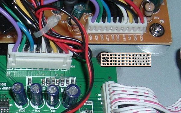
The next stage is powering the fan. Tap the power from the wires on the connector on the board. Don't tap the power from the board directly. Find the +12 volt supply. On the MX this is the Blue wire as shown below. On the MS this is the orange wire closest to the rear of the machine on the connector. The ground on both is the Black wire closest to it.

That should be it. Now confirm all connections and make sure you haven't left anything inside the unit that could short. Power up the unit and confirm that it still turns on and goes beyond the night rider stage.
For the MX receiver create a small board from perf board and place the Header on it. Then solder the wires as shown below. You will be able to solder from the points indicated in the board and run the wires to the header. You can then use the above JTAG cable for either machine.


The BFL ( Boot from Link) jumper (115)should be connected as shown below
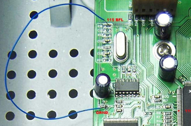
This is used to add full control of the CPU for writing. If you experience problems with DCU errors in Jkeys, this will probably solve it.
I would mount the board here as shown above. Remove the corner screw and place the header board on top then put the screw through the perf board and re tighten it. Make sure the points underneath the header don't touch the case bottom. Also put some tape on it as a precaution against shorts underneath when you attach the JTAG cable. Make the wires as short as possible and keep them organized.
If everything is ok you can proceed to the programming section.
PROGRAMMING
Connect the serial cable from your com1 on the computer to the receiver.
Find the following:
pansat loader ver 3.20 or STB loader or BL Loader
Boot60.bin ( In the cleaner zip file)
Factory Bin for your machine
The new Bin you want to load
GTOOLS
Your TID active channel list. ( if you use a TID active list your EPG will work)
Many of these units are somewhat quirky in the sense that they may not react well to certain programs. I have worked on many similar units that will and won't load certain software. Try until you have success.
Open the program and choose the Boot 60.bin file. Download the file to the receiver and wait until complete. Don't do anything on the computer until this completes. Any interruption the receiver doesn't like and your in JTAG hell. Once completed the receiver will reboot and you will have only night rider lights. Next load the factory bin. there is a good chance that you will get night rider lights once more. I would let this run for a few minutes.. Feel the heat from the unit and see how hot it gets.
Now load the new bin. Again don't be worried or surprised if the bin doesn't load or the file errors, wait for the reboot ...just try again with a different loader.
Now open GTOOLS and load the channel list. Choose Tools, STB Connect, a box will appear to allow you to download the file to the receiver. Its a good idea to keep your file in the computer and your channel list in the receiver up to date.
Remember that Download=machine to receiver and Upload=receiver to machine.
For this step of the procedure, you will need some software. Download the following.
Make a directory on your C drive and call it SAT. Inside the SAT directory make 4 directories. JKEYS, Walls, Loader and Bins. Expand copy the appropriate files to their directories.
Jkeys.exe Find it here Use this version as I find it works best.
Jkeys.def Find it here! Copy this file into the JKEYS.EXE directory only if you can't find the right IRD model in the next step.
Walls.exe Find it here
Pansat Loader v320 Find it here (Down load the Pantec MS all you need.zip)
X-8500_040916_235_api(Bl).bin ( factory Bin File) Find it here
You will also require the 9 pin female to 9 pin female serial ( Straight through) cable that came with your receiver.
Procedure:
Connect the JTAG cable to your computer parallel port and then plug in the 10 pin connector to the receiver. Plug in the receiver but keep the power switch off.

Turn on the receiver. Run Walls.exe. Reset the CPU by clicking on "RESET uP", Click on "RESET EJTAG", "Refresh Items" then close the program
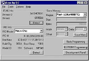
Run JKEYS you should get a window similar to the one above.
Make sure you get a similar screen. That will let you know if
you have your JTAG connected right.
IRD Modal = Macrx Chip
Region = Flash 1(29LW800BTC)
If you don't see Macrx in the IRD model window..
Click the pull down tab and select it.
If its not there, go back and download the JKEYS.def file and copy it into the JKEYS directory. Repeat the last step.
Still having problems ..go Here
To dump your flash chip click on Save Mem.
(This isn't absolutely necessary but a
good idea.)
You will get a dialog box like the one below.
Simply click save, and you will begin the dump process.
You can call it anything and put it anywhere you will remember.

To program the Flash chip you will click on the Flash Programming button.

You will next get a warning dialog as shown below.
Simply click the OK button to access programming functions for the the flash chip.

In the programming window you will use the Erase,
and Program functions (Chip/Sector Programming)
make sure the pull down box is set for Full. First
you erase the flash chip then you use the Program
button to rewrite
new firmware to the flash chip.
IRD Modal = Macrx Chip
Flash = Flash 1(29LW800BTC)

When you click the Program button you will get a
browse box so you can find the firmware file to
write to the receiver. Simply click open once you
locate the file Blacklist X-8500_040916_235_api(Bl)( factory Bin File),
and programming
will begin. Don't select the
new bin file yet as this will come next.
A progress bar will appear. Wait for this to complete and then switch off the receiver. Now turn on the receiver and look at the front of the unit. The display should light up. Turn off the receiver and disconect the JTAG cable and replace the cover and the 5 screws.
Programming the Autoroll Flash:
The next step is to flash the receiver using the serial cable that came with your receiver and the Pansat Loader v3.20 with the new bin. Plug the serial cable into com 1 and the other into the receiver. The receiver should be switched off but plugged in.
Run Pansat Loader v3.20.

In the STB Model Box type " Pansat 2500A " . Load the Bin File. Choose the new bin file from your favorite source.
Make sure the file type is Flash Rom File. ( This is why we didn't use JKEYS for the upgrade flash) Turn on the receiver switch on the rear. Click download.
The process window will appear. Allow the process to complete. Don't touch anything until the completed box appears.
If an error message appears, repeat the process. Once completed turn off the receiver. Unplug the serial cable. Turn on the receiver. If the receiver lights up then all is well
Reconnect your cables and reconnect the antenna and AV cables and re program your sat channels.
TROUBLE SHOOTING.
1) If you have problems with the software running on XP use Windows 98. The comctrl32 used in XP may effect the operation of the VB scripting. You will know this if your LED's don't light or light properly.
2) If you can't find the Macrx IRD choice in JKEYS then download the JKEYS.def file, or open the current JKEYS.DEF file in notepad. Add the following to the end of the file...
IRD, 21, "Macrx Chip", 8, 1, 1, 1, 2, 2, 0x7FE00000, 0x7FEFFFC4, 0x7FEFFFFE, 0x7FEFFFA8, 0x7FE74FF4, 0x7FEEFFC7, "Ult", 0, 0 IRDFlash, 21, "Flash 1(29LW800BTC)", 0x225B, 0x7FE00000, 0x100000, 2, 2, 0
Note the IRD number is the order in the list...so if your last IRD in the list is 12 then the above line will start with " IRD, 13,"Macrx... etc and the IRDFlash, 13, "Flash 1(29LW800BTC) etc. Save the file as JKEYS.DEF obviously.
3) Don't upload the new auto-roll flash as a Boot File.

