How to Chip a Honda 92-95 ECU
DA
FUTURE does not assume any responsibility for the use of this document or
its information.
Here is a step by step guide toward installing a racing chip on 1992 to 1995
Honda OBD-I ECUs. First, open up your ECU top cover.

Figure 1
OBD-I USDM and JDM ECU
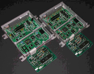
Figure 2
Remove Top Cover
- Open the top panel of the ECU. Figure 2 is a
view of the ECUs Components side. The AT JDM ECU (right) has a Stock
ROM a 28 pins chip with the marking Oki M27256-17 with golden sticker and
number 73 no top. It is at the lower left corner away from the ECU Plug (top
view, you will have to unscrew the top circuit board P30 only to spot it).
As for the MT JDM ECU there is blank space on the same location
marking 27256.
- Desolder the stock ROM Figure 3 on the AT
JDM ECU like other OBD-0 ECU and solder in place the 28 pin IC socket and
plug in the new chip that's just all to easy to chip.
- On the MT JDM ECU Figure 3 you will need
addition parts to chip these ECU. The first item is a SOP-20 small outline
74HC373 20 pin chip. Fine solder them to the top of the 28 pin IC Socket
(red circle). Make sure you don't overheat these small chip and make sure
you got the pin 1 in the right position.

Figure 3
Lower left corner of the ECUs |
|
- Now you need to bridge the jumper. Figure 4 show the solder side of
the ECU. Spot the J1 location in the center of the ECU circuit. Bridge this
jumper with SMD 0 ohm resistor or just thin wire. Now you are have just
switch the Oki 66207 processor to external memory mode and ready for any
racing chip.

Figure 4
The J1 jumper on the back of the ECU
Now for Long USDM ECU Like P28, P30 DelSol. Figure 5
shows a P28 ECU being.chipped. First install a 74HC373 chip at upper right
corner of the ROM location (optional using 20 pin IC socket). Solder in place
the 28 pin IC socket for the new EPROM. Add two capacitors 103 ceramic type in
location C51 and C52 (these are optional). Add a 10K ohm resistor in location
R54 and jumper on location J1. Now you are ready to plug in the new EPROM.

Figure 5
Chipped P28 ECU
- Insert the New Chip or the old stock chip in the 28 pin IC
socket. After that, just reinstall the ECU top and bottom
covers. Plug the ECU back on the car, reconnect back the battery positive
terminal and start the car to check whether the car is runing fine.If you
don't any check light and able to rev pass 4000rpm, you have just
successfully chip your ECU.
For Long USDM ECU Like P72 GSR. Figure 6
shows a P72 ECU being.chipped. First install a 74HC373 chip at upper right
corner of the ROM location (optional using 20 pin IC socket). Solder in
place the 28 pin IC socket for the new EPROM. Add jumper on location J10.
Now you are ready to plug in the new EPROM.

Figure 5
Chipped P28 ECU
- Insert the New Chip or the old stock chip in the 28 pin IC
socket. After that, just reinstall the ECU top and bottom
covers. Plug the ECU back on the car, reconnect back the battery positive
terminal and start the car to check whether the car is runing fine.If you
don't any check light and able to rev pass 4000rpm, you have just
successfully chip your ECU.

