
Enclosure Modelling
Using the measured electrical and
mechanical parameters, we can begin modelling different enclosure alignments.
Both of the woofers used here have a relatively low Qts value, which suggests
they be used in a vented enclosure. There are several different alignments
that would all give good results. The main/surround design ended
up having an internal volume of 0.50 cuft. This is before internal
bracing and driver volumes are subtracted. After subtracting the
volumes of the internal bracing, port and driver structure, the internal
volume comes out to around 0.48 cuft. The enclosure is designed with
a sloped front baffle. The baffle is slanted at seven degrees.
There are several reasons that a slanted baffle is desireable. First,
it helps bring the drivers' centers closer to being on the same vertical
plane. Second, it helps minimize some of the internal standing waves,
by breaking up some of the modes that develop in a standard rectangular
enclosure. The basic dimensions of the enclosure will be 8-1/2" W
x 13-1/2"H x (11"T, 12-3/4"B)D.
The enclosure, tuned to about 40 Hz, should give a lower cutoff of about 44 Hz, which is pretty good for a 6-1/2" woofer. I've used this woofer in larger enclosures and gotten down to the mid 30s, but the transient response wasn't too great. Here, we should have a much tighter sound. I had toyed with the idea of using a shelf port, but after further consideration, I've opted for the more traditional plastic tube port. To avoid coloration due to port turbulance and some other anomolies, the port is placed on the back of the enclosure. As long as these speakers are kept atleast 6" out from the wall, this shouldn't be a problem. The port has an internal diameter of 1-1/2". Ideally, a slightly larger diameter port would be preferred, but these ports incorporate a large radius flare on the exiting edge. This should help minimize the turbulence that can sometimes occur in smaller diameter ports.

Predicted frequency response for the main/surround speakers.
The center channel design uses two 5-1/4" woofers, which effectively gives an overall 3 dB gain over a single woofer. The center channel also uses a vented design, with an internal volume of 0.90 cuft. The enclosure is tuned to 43 Hz using two 1-1/2" I.D. ports. This will give a lower cuttoff of about 48 Hz. This speaker will be placed on a shelf above my TV inside a bookshelf. In this case, I'm opting to put the ports on the front baffle to avoid coloration due to the chamber nature of the bookshelf. The center channel enclosure is larger than most, at 26-1/4"W x 7-1/2"H x 12"D. These dimensions were chosen so the center channel is roughly the same width as my 27" TV. For this application, the speaker will be placed above the TV, and slightly above the main speakers. If a slanted baffle were used here, the listener would always be listening to the speaker considerably off-axis, which would likely result in a fair amount of attenuation of the highest frequencies. Also, the time alignment benefits would be almost non-existent due to the very small vertical center-to-center spacing. Thus the standard rectangular box.
Predicted frequency response for the center channel speaker.
Crossover Designs
Both woofers are fairly inexpensive,
and a typical side effect of cheaper woofers is lack of midrange clarity.
The 6-1/2" woofer simply lacks midrange output, whereas the 5-1/4" has
a fairly grainy midrange. From the experience of others, it is best
to cross both of these drivers over fairly low. To maintain a safe
crossover point between the woofers and tweeters, a crossover point of
2350 Hz was chosen for the main and surround speakers. This is a
safe crossover frequency when using the Dayton tweeters, but I'm told the
Vifa sounds better if crossed higher. Ideally, the Dayton 5-1/4"
woofers would be crossed at 2000 Hz or less, and the Vifa's at 3000 Hz
or higher. The compromise of 2500 Hz is chosen. This will certainly
provide adequate protection for the tweeter, but may not be the greatest
choice of all possible crossover frequencies. These are the compromises
that must be made when working on a limited budget with limited resources.
We will be aiming for 4th order accoustic slopes in all of the crossovers.
For the center channel, this means 2nd order Linkwitz-Riley topologies.
The main/surround crossovers were designed using powerful simulation and
optimization software. The basic topology there is 2nd order for
the low pass, and 3rd order for the high pass. This method is able
to account for some of the time delay due to the fact that the tweeter's
and woofer's accoustic centers are offset. In all, the main and surround
crossovers provide very flat on and off-axis response, each driver rolls
off very close to the target 4th order, and the phase tracking near the
crossover point is excellent.

This is the crossover for the main
and surround speakers, designed by Wayne Jaescke using CALSOD. It
is obviously a complex design, and intended to get the maximum possible
performance out of the drivers. It uses all poly caps (except the
film and electrolytic in the Zobel) and 18 ga inductors (except for the
16 ga foil in the lowpass). The crossover also includes a parallel
notch filter to even out the resonance peak around 3-4 kHz. Can you
say "no holds barred?"
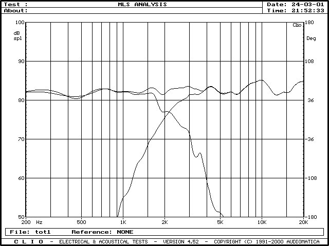
Here is the actual measured response
of the individual drivers, and the summed response. As you can see,
it is very flat all the way from 200 Hz to 20 kHz. There is a slight
hump around 10 kHz. This graph has been normalized to 1W/1m, and
the overall sensitivity is about 83 dB. Hats off to Wayne!
This is the crossover for the center
channel. It uses "cookbook" Linkwitz-Riley values based on the drivers'
nominal impedences. There is also a Zobel network to flatten the
woofers' inductive rise. The woofers are wired in parallel and the
tweeter's phase should be reversed (as shown in the schematic). Again,
all capacitors are poly (except the electrolytic and film in the Zobel),
and all inductors are 18 ga. Considering no measurement equipment
was used, and a less than ideal crossover point was chosen, the results
are surprisingly good.
Most woofers fall prey to something called inductive rise. The voice coil of a woofer acts as an inductor, so as frequency increases, the resistance also increases in an exponential fashion. This is a bad thing, because when designing a crossover, it is assumed that the driver presents a constant resistance. In order to compensate for this rise, a simple R-C filter, called a Zobel network, is used to level the impedence rise.

This is a simulated response of the
6-1/2" woofer without a zobel network and the "textbook" components
for a 2nd order L-R filter at 2500
Hz. Due to the impedence rise, there is a noticiable hump around
1800 Hz.

Here is the same crossover, this
time using a simple R-C (Zobel) network to compensate for the woofers
inductive rise. The rolloff
is now much closer to the 2nd order slope we were shooting for.
