
Figure 1 Simple 0 to 500 Volt Adjustable power supply.
For a verbal description click here.
In this article I will first examine what constitutes a bench power supply. Next I will discuss variability, regulation, and the combination of both to make a regulated variable supply. Next I will describe various circuit configurations on the block diagram level for regulating and adjusting the DC output of a power supply. Finally I will provide circuit diagrams from various hobbyist sources and successful commercial products.A Bench Power Supply.
A bench power supply needs to provide any and all voltages that may be needed on the bench for breadboarding and testing electronic circuits or troubleshooting a malfunctioning instrument. With such broadly defined requirements you could go crazy listing what you might need.
- 3.5 and 5 volt DC at high current for logic and CPU circuits.
- 9 V to 36 V DC low current well regulated and filtered for small signal transistor and integrated circuits.
- 25 V to 100 V high current for IC and transistor power circuits.
- 50 to 500 VDC at up to 200 mA for plate and screen circuits of moderate power vacuum tube circuits.
- 0 to -100 VDC for vacuum tube grid bias.
- 300 to 2500 volts at 1 A for high power vacuum tube circuits such as transmitters.
- 1000 to 5000 VDC at a few mA for cathode ray and photo multiplier tubes.
- A wide variety of voltages ranging from 1.5 to 120 volts at currents ranging from 50 mA to 10 A AC or DC for filaments and heaters of vacuum tubes.
A single unit with all that would be bigger than the bench it services. So clearly we need to place limits on our power supply design. The site we are on is called Fun With Tubes so we can eliminate the transistor and logic part of the monster. Work with high power RF or AF circuits is a specialty among engineers so the high power part would consist of a special supply for that purpose alone. Same goes for engineers specializing in the fields that use CRTs and PMTs so they are gone. The complexity of filament and heater voltage switching can be eliminated because most work with tube circuits is done with tubes that have 6.3 or 12.6 volt heaters. The occasional tube circuit needing different heater/filament voltage can be accommodated by a temporary lash up employing a filament transformer or a transistor power supply. So here is what we really need.
- 50 to 500 VDC at up to 200 mA for plate and screen supplies of moderate power vacuum tube circuits.
- 0 to -100 VDC for vacuum tube grid bias.
- 6.3 and 12.6 VAC at a few amps for tube heaters.
We now have a manageable power supply that can sit on a bench or its equipment shelf. Also it won't require a fork lift to place it there or 3 phase power to juice it up.
Variability and Regulation.
Many people make the casual assumption that if a power supply has variable voltage output, it must also be regulated. If you think that, focus your baby blues on figure 1 below the next heading. Not all adjustable power supplies are regulated and not all regulated power supplies are adjustable.Variable Voltage Power Supplies.
The simplest form of variable voltage, also known as adjustable, power supply is shown in figure 1.
Figure 1 Simple 0 to 500 Volt Adjustable power supply.
For a verbal description click here.
The symbol between the two switches is a variable transformer. Variac is a registered trademark. A 1 amp transformer is about right in this application. A much higher current supply could be made this way by increasing the current capacity of the variable and plate transformers and the filter choke.
The 3 kV capacitor across the transformer secondary is to suppress diode blowing transients that are produced when the high voltage switch is opened. This is not a theoretical based speculation. I have blown diodes in a setup like this without the capacitor. Vacuum rectifiers are not as fragile as silicon diodes so you never see this capacitor in all tube circuits.
Note that neither side of the DC nor Heater supply is connected to the chassis. The terminals are brought out to the front panel and a chassis grounding connector is next to them so the user may ground either side of the supply. Grounding is strongly recommended unless it creates a ground loop.
This is a good simple circuit but it is not regulated. As more current is drawn by the load the output voltage will decrease. This is termed load regulation and is defined as,
Load Regulation = 100 (VNL - VFL ) / VNL Where VNL is the voltage with no load and VFL is the voltage at full load.
And while we are defining terms line regulation is defined this way,
Line Regulation = 100 (VLMAX - VLMIN) / VLMAX Where VLMAX is the power supply output voltage at the maximum line voltage and VLMIN is the power supply output voltage at minimum line voltage. On my workbench the line voltage changes by less than 3% so load regulation is a much greater effect than line regulation. Load regulation will be 10% even for a very good power supply. 15 to 20 % is much more common.
Another form of making an adjustable voltage power supply involves the use of tubes as shown below.

Figure 2 0 to 400 Volt Adjustable power supply using Tube(s).
For a verbal description click here.
Although the tube is shown as a triode a pentode may be as easily used. One tube has been shown for simplicity but 2, 4 or as many as needed may be connected in parallel.
The advantage of this circuit is that it provides ripple filtering without the need for a heavy filter choke. The disadvantage is that when full current is being drawn at low output voltage the current drawn from the power line is the same as if the supply were delivering full load current at maximum voltage. In the case of figure 1 the power drawn from the line decreases as the output voltage is reduced while the current draw remains constant. The pass tube must dissipate the extra power. Think of the unlikely case where you want to supply a load with 10 volts at 200 mA. The power in the load will be 10 V x 0.2 A = 2 watts. The dissipation of the pass tube(s) will be 490 V x 0.2 A = 98 watts. That is an extreme situation but those who design commercial power supplies must account for the fact that if something can be done some idiot, er, person will do it. There are ways of mitigating this problem and they will be covered in a later section.
Another way of making an adjustable power supply is to use SCRs (silicon controlled rectifiers) or triacs but this is fun with tubes not fun with triacs. The glass equivalent of an SCR, the thyrotron, could be used but they seem to be available only in power levels of a few watts or many kilowatts and nothing in between.
Regulated Power Supplies.
An automatic regulator consists of 4 basic parts.
- Reference.
- Comparing Device.
- Error Amplifier.
- Controller.
The block diagram is shown below.

Figure 3 Block diagram of a generalized linear regulator.
For a verbal description click here.
This diagram applies to any analog or linear automatic regulator device.
The Reference is the setting of the desired output. It might be the setting of a thermostat or the setting of a cruise control.
The Comparison Device compares the temperature of the oven with the setting of the thermostat. In a cruise control the actual speed of the car is compared to the setting of the cruise control. The comparison device generates some kind of indication that the controller output is different from the reference and in which direction. This is often called the error signal because it is proportional to the error by which the controller is off from the reference.
The purpose of the error amplifier is to increase the magnitude of the error signal so it will have the desired effect on the controller. In many applications the comparison device and amplifier are combined into one electronic or electro-mechanical unit.
The Controller is what does the heavy lifting as it were. It controls the amount of power delivered to the heating element of the oven, or the amount of throttle to the car's engine.
In a regulated power supply the reference is a voltage source that is so designed as to be immune to changes in line voltage and load current. While in the above examples the temperature setting of the oven thermostat or the speed set on the cruise control are the reference values, in a power supply the reference is fixed and the voltage must be adjusted by other means. In the simplest power supply regulator the comparison and amplification are accomplished by a single tube making them inseparable. In more complex circuits it is possible to point out two tubes and say these make up the comparison circuit and one or more other tubes make up the amplifier. The controller must by nature be a power tube. It is always in series with the load and the unregulated power supply.
Note: There are power supplies that use shunt regulators for some special purposes. They are found more often in silicon based circuits because the usual failure mode of a transistor is shorted. If the pass transistor in a series regulator goes short the full voltage of the unregulated supply is applied to the load. This is likely to be fatal to the load. If the regulating transistor is in parallel with the load a short will result in zero volts across the load. The load stops working but after the shorted transistor has been replaced the load returns to its normal function.
The unregulated power supply consists of the power transformer, the rectifier, and one filter capacitor. Such a supply will have a considerable amount of ripple at high current loads but the regulator will regulate out the ripple the same as it regulates out slow changes in line voltage, by constantly correcting the output voltage.

Figure 4 Diagram of Simple Voltage Regulator.
For a verbal description click here.
In this circuit the lower triode serves as both the comparison device and amplifier. The vr tube holds the cathode voltage at 105 volts. In order for the tube to be conducting some current but not too much the grid must be within a couple of volts and negative with respect to the cathode.
The upper triode is the pass tube. Its grid must also be negative with respect to its cathode so the end of the 100 k ohm resistor which is away from the plate of the tube is connected to a voltage that is always positive with respect to the plate of the amplifier tube.
Suppose that the power supply is delivering 20 mA to a load and the user connects an additional load to bring the load current up to 200 mA. Seen on a very short time scale the output voltage will drop a little. The voltage at the grid of the amplifier will go in the negative direction making it a little more negative. The plate current of the amplifier will be decreased causing the plate of the amplifier along with the grid of the pass tube to move in the positive direction. A new equilibrium will be established with the output voltage corrected to its original value, almost.
For the fixed resistor values shown the output voltage will be very close to 3 times the voltage of the vr tube. The correction does not take place instantaneously but it can be very fast. Changes in the plate voltage of the pass tube whether they happen rapidly is in ripple or slowly as in a change in line voltage around the cooking hour will be continuously corrected for by the amplifier. The amplifier tube is much more likely to be a pentode than a triode. A triode is shown to avoid the additional complexity of the screen grid supply.
This is not an adjustable supply. You might think that all you have to do is put a pot in the grid circuit of the lower triode but there are limits. First of all even if it were possible for the voltage between plate and cathode of the lower triode to go to zero the lowest voltage available would be the voltage of the VR tube, 105 volts + the grid bias of the pass tube. The voltage across the tube will not go to zero so the minimum output voltage of the regulator is the VR tube voltage plus about 50 volts.
Second the lower triode is a small signal tube and it may have a maximum plate voltage of 250 volts. If the VR tube is a zero B 2, 105 volts, The maximum output voltage of the power supply is therefor, 355 volts. (Note: This limit is broken much more often than it is honored. More on this later.) So if a 105 volt regulator is used the voltage can be adjusted over the range of approximately 155 to 355 volts. So if you have a supply like this and you need 125 volts or 400 volts your out of luck.
Variable Voltage Regulated Power Supplies.
The power supply in figure 4 can be improved by moving the B negative point from the cathode of the vr tube to the cathode of the amplifier tube. This makes it better but not perfect.

Figure 5 Adjustable Regulator with Improved Range.
For a verbal description click here.
Figure 5 shows an improvement on the circuit of figure 4. The VR tube has been changed to one which has much less voltage drift and change as the current changes. It operates over the current range from 1.5 to 3.5 mA which makes it much less power hungry. The operating voltage is 85 volts. I tried finding values for resistors R3 and R4 from the much touted "PSU Designer II" from a source which I have forgotten. The program doesn't want to tell me where it came from either. Anyway I couldn't get values I could believe and the graph isn't working right so I don't trust it. My own program didn't fare any better. If you want to duplicate this circuit you will have to breadboard it and trial and error the values of R3 and R4.
The resistors labeled R1 and R2 are usually internal adjustment pots connected as rheostats. Their effect is counter intuitive. R1 adjusts the minimum voltage while R2 adjusts the maximum voltage. The amplifier tube limits the minimum voltage. 50 volts is a typical value. The maximum voltage is determined by the ripple valley voltage and the minimum drop across the pass tube(s), both measured at maximum load current.
I wrote earlier about the maximum plate voltage of the amplifier tube. This value is honored more in the breach than as the maximum. Both Heath and Eico made power supplies with very similar schematics. Heath used a 6BH6 and Eico used a 6AU6. Both tubes have a maximum plate voltage of 300 volts but in both supplies when the output is set at maximum, 400 volts, the plate voltage on the amplifier tube is 550 volts. The tube in my Heathkit IP17 has never flashed over although I have put many hours on it operating at its max voltage of 400 volts. I will give a simplified version of the Heath/Eico circuit in the next section.
Determining the Minimum and Maximum Output Voltage.
You can always build a power supply and then run tests on it to see how high and how low the output voltage can go. Most likely you have a set of rough specifications in mind and if the finished power supply doesn't meet or surpass them you are going to feel disappointment and probably some additional emotions.There are two factors that affect the maximum voltage. They are (1) The ripple valley voltage of the rectifier/filter, and (2) the minimum plate voltage of the pass tube(s).
Ripple Valley Voltage.
You may never have heard of "ripple valley voltage". An exception would be if you have studied my on line textbook titled "Electronics for Non-Engineers" or you enrolled in my course at Western Kentucky University in the years I was teaching there. The almost universal use of integrated circuit voltage regulators has made it a very important concept yet few people have ever heard of it and fewer still understand it.

Figure 6 Schematic of Rectifier and Filter with Output Waveform.
For a verbal description click here.
Everyone knows the meaning of peak whether in mountains or voltage waves on a scope. How about valley? Everybody knows the meaning of valley in terrane. Right? What about the wave represented by the heavy red line? Do you see a valley there? It's the minimum voltage but will only be negative if the whole wave is turned upside down as in a negative power supply. The thin black lines represent what the output would look like on a scope if the capacitor were absent. Adding the capacitor causes the output to become like the red line. The black lines wouldn't show up on a scope unless you have a fancy schmancy storage scope. The wave would be above zero for a positive supply
In this figure the resistor represents the load which is the complex circuit of the regulator and its load which may also be complicated such as an audio amplifier or radio circuit. In the following the load will be characterized as a constant current rather than a resistor. This is not without rational justification.
The regulator maintains constant voltage across the load. If the load is not itself changing than its current draw will be constant. That means the current drawn from the rectifier-filter is a constant. Note: We wish to evaluate the performance of the rectifier-filter under steady state conditions. Therefor a changing load such as a class B amplifier is not allowed. Let's see how we can calculate the valley voltage. Remember this one?
i = C dv/dt. Where i is the time varying current in amps, C is the capacitance of the capacitor in farads, and dv/dt is the derivative of the instantaneous voltage with respect to time. Now if we let the current be a constant it makes my spell checker happy because it no longer has to tolerate a lower case I but I don't think the grammar checker will ever be happy.
I = C ΔV / Δ t Where I is the current in amps, C the capacitance in farads, ΔV is the change in voltage for a given time interval, and Δt is the given time interval. So then
Ripple Valley Voltage = VP - Δt I / C Let's see what the values we have been casually tossing around will give us. VP = approximately 500 volts, and IL max = 200 mA.
Ripple Valley Voltage = 350 x square root of 2 - 8 x 10-3 x 0.2 / 220 x 10-6 = 488 V. So why did I use 8 ms instead of the exact value of 8-1/3 ms? Look at the picture. The recharge often called the top off time is short. In the drawing the top off time is rather long as is the value of ΔV. For the rather small value of ΔV in this example the approximation of 8 mS is probably rather good. For larger values of ΔV the results of the equation will give a pessimistic value of the valley voltage which is better than an optimistic one.
(Note: I have spent many hours at my desk accounting for charging time to obtain the exact equation for discharge time and many additional hours in the lab attempting to verify the mathematical results. All to no avail. It does not appear possible to obtain an exact equation. In my lab work I did account for actual capacitor values but it didn't help very much. In the real world the electrolytic capacitors used as power supply filters have a value tolerance of -10% to + 30%, 40%, or sometimes even 50%. Power supply calculations are an approximation and a safety factor should always be a part of the design procedure.)
This does not mean that we can run the output voltage of our power supply up to 488 volts. That would call for a drop across the pass tube of zero volts. Sorry, that's just not happening. What is the minimum voltage? That depends.
Let's try it with two 6080 tubes in parallel. This is a dual triode especially designed for use as the pass tube in regulated power supplies. Each section is good for 125 mA so you would think that one would be enough. After all it would be good for 250 mA. OK, we'll look at it for one and two tubes.

Figure 7 Plate Characteristics of 6AS7G/6080/6080WA, one section.
For a verbal description click here.
Maximum Output Voltage.
What we need to do is to determine the voltage drop across the pass tube for zero grid voltage and the maximum specified current. If we use one tube the current in each section will be 1/2 of 200 mA or 100 mA. The voltage drop for 100 mA looks to be pretty close to 50 volts. For two tubes the current for each section is 50 mA and the voltage appears to be about 1/3 of 50 volts which is about 17 volts. Given the valley voltage of 488 volts for a single 6080 the maximum output voltage is 488 - 50 = 438 volts. For two tubes the maximum output voltage is 488 - 17 = 471 volts. For a production unit the value of the filter capacitor could be somewhat reduced for lower cost. For a single hobbyist unit a few tens of cents won't make that much difference.Maximum Pass Tube Dissipation.
Think we are doing pretty good at meeting our specifications? Think again. The maximum plate dissipation for the 6080 is 13 watts per plate or 26 watts for both sections. I didn't find any information about derating when the tube is used with both sections in parallel. So for a plate current of 200 mA the maximum plate to cathode voltage is 130 volts. (Note: We earlier calculated the ripple valley voltage to be 488 volts and the peak to be 495 volts. The average of these two values is 491.5.) That means when the plate is at an average voltage of 491.5 volts the lowest the cathode can safely go for a load current of 200 mA is 491.5 - 130 = 361.5volts. Of course the current can be derated for lower voltages. For example for a current of 100 mA the maximum plate to cathode voltage is 26 watts / 100 mA = 260 volts. That will bring us down to 231.5 volts. At this point we have already exceeded the maximum plate voltage of 250 volts but it does appear that maximum plate voltage ratings were made to be exceeded.This makes the case for using two tubes in parallel. The plate dissipation is now 52 watts and the maximum plate to cathode is now 260 volts which gives an output of 231.5 volts. At our minimum output voltage of 50 volts the current must be derated to 118 mA.
Minimum Amplifier Tube Plate Voltage.
The absolute minimum output voltage of our power supply is set by a combination of the pass tube and the amplifier tube. Let's say we are going to use a 6AV6 as the amplifier tube.

Figure 8 Plate Characteristics of 6AV6, Triode Section.
This graph is somewhat similar to the one in figure 7 but the curves
are leaning more to the right. The zero volt curve is slightly convex.
Since there are two variables effecting the minimum voltage and there aren't equations for them we must do some trial and error. So we will guess that our minimum voltage will be 50 volts. Seems like a nice round number. This is an approximation so all other numbers will be also. The voltage drop across the pass tube will be 350 volts. That's just the first one. The derated current at this output is 120 mA. Estimating the grid voltage for the two tube design based on the plate curves, the amplification factor of 2, and a lot of extrapolation gives a voltage of -190 volts. With this much voltage between grid and cathode of the pass tube it is impossible to get the cathode voltage down to 50 volts. The grid would have to be at -140 volts. What we have here is a regulator that won't work.
If the cathode of the amplifier tube were to be set at say -200 volts the large negative grid voltage would not be any problem. The heater of the 6AV6 would have to have its own private winding and possibly other accommodations would be necessary but a regulator with this tube is not beyond the realm of possibility. As we will see in later sections an adjustable regulated power supply equivalent to the HP 712B is not simple.
This circuit could be made to work as a fixed voltage regulator. In fact HP and Tektronix engineers did it many times. The 6080 is not a good choice for a regulator that is to be varied over a wide range of output voltage.
Let's Do It With Pentodes.

Figure 9 Same Regulator as Figure 5 But Using Pentodes.
For a verbal description click here.
Notice that we now need an additional winding on the power transformer to serve as a floating screen supply for the pass tubes. If the screens were simply connected to the plates the 6L6s would operate as triodes. Let's look into that.
Triode vs Pentode Operation Of the Pass Tubes.
Here are the plate characteristics for the 6L6 connected as a triode.

Figure 10 Triode Characteristics of 6L6GA.
This graph is in many ways similar to figure 8. Verbal descriptions of these 3 parameter graphs would be very long and difficult to write and equally difficult to absorb and understand. If you should have need of it for a school or university project please contact me and I will turn one out for you. But you should avoid riding a good horse to death.
Note: As far as I am able to determine the characteristic curves for the 6L6G through the 6L6GC are identical. Only the maximum ratings have been changed to protect the innocent.
Here are the plate characteristics for the 6L6GA connected as a pentode. I chose this graph from the tube manual because the screen voltage used is the same as that used by the Heathkit IP17 power supply.

Figure 11 Pentode Characteristics of 6L6GA.
For a verbal description click here.
It is a given among engineers that when the pass tubes are connected as pentodes the regulation is better than when they are connected as triodes. However, my initial attempts to prove this by the numbers taken from the curves met with failure. I tried comparing the gain of the pass tubes as a cathode follower which yielded only a small percent difference. Same went for the transconductance, 5 millimhos for the triode and 6 for the pentode. I did not use tube manual numbers but picked values from the graphs as close as possible to the actual operating point.
A somewhat less rigorous comparison is to look at the grid voltage change for a current change from 50 to 5 mA. Remember that in our so far mythical power supply, there are 4 6L6GC tubes in parallel. This change represents a total load change from 200 to 20 mA.
Looking at the triode curves the point 300 V, 50 mA is about 2/3 of the way from -15 to -30 grid volts. So let's call it- 25. The point 300 V, 5 mA is about 10% of the way from -45 to -30 so let's call it -43.5. So the grid voltage change is 18.5 volts.
For the pentode the point 300 V, 50 mA is at a grid voltage of -19 volts. The point 300 V, 5 mA the grid voltage Is -30.9 volts by interpolation. That sounds a little too precise considering the nonlinearity of the curves at this low current. Let's call it -31 volts. That gives a change of 12 volts.
So we have 18.5 for the triode and 12 for the pentode. That's a change of 35% for pentode as compared to triode. That's pretty good compared to other measures but I think the absolute value is even more important. For a current of 5 mA the grid voltage was -43.5 for the triode connection and -31 for the pentode. That gets our minimum voltage 12.5 volts lower when pentode connection is used.
But the most compelling argument is this. When the operating point of a pentode moves out onto the flat part of the plate curve the plate current is effected very little by changes in plate voltage. This makes the pass tube(s) almost immune to ripple and line voltage changes even if there were no feedback regulation. The main effect of load changes is to bring about changes in the output voltage of the rectifier filter and as already explained the pass tube(s) are highly immune to these changes.
Maximum Output Voltage.
The maximum output voltage corresponds to minimum plate voltage of the pass tube. Looking at the 6L6 curves we see that for a grid voltage of zero we can get down to about 20 volts for 50 mA per tube. Note that the scale is 15 volts per horizontal division. But there is more going on than just the plate voltage and current. The screen current for 20 volts on the plate is about 65 mA. If the screen voltage remained at 100 250 volts the screen dissipation would be 16.25 watts. Maximum for the 6L6GC is 5 watts so the screen would be melted down in pretty short order. But the voltage will not be constant at 250 volts because there is a 1 k ohm resistor in the filtering circuit. Let's say that the screen current rises to 20 mA. The drop across the 1 k resistor will be 20 volts giving a screen voltage of 230 volts. The operating conditions of the tube have now changed and the curves are no longer valid. But they are all we have. 20 mA at 230 volts gives a power of 4.6 watts. That's about as high as we should go. It's hard to see but it looks like the dashed line crosses the 20 mA line at 60 volts. So we can safely take the plate voltage down to 60 volts. The ripple valley voltage calculated above was 488 volts so we can get the output voltage up to 488 - 60 = 428 volts. So we can meet the maximum voltage specification of 400 volts with some to spare.Minimum Output Voltage.
If it were possible for the plate voltage of the 6AU6 to get down to zero the cathode of the pass tubes could get down to 31 volts. If the grid voltage is zero the cathode is 31 volts more positive for a current of 5 mA. It is impossible to say what would happen at lower currents. I would need my own vacuum tube curve tracer to evaluate the 6L6 at small values of cathode current. I haven't built one yet. Here are the plate characteristics for the 6AU6.

Figure 12 Plate Characteristics of 6AU6A.
As you can see for a control grid voltage of zero the screen grid current reaches 4.2 ma at a plate voltage of 100 volts. Yes, but that's only if the screen voltage is held at 100 volts. Looking back at figure 9 the screen of the 6AU6 is supplied through a voltage divider from the 500 volt unregulated supply. The values of 390 k and 100 k ohm give an unloaded voltage of 102 volts. The output resistance of this circuit is the parallel combination of the two resistors which is 79.6 k ohms. The plate characteristics don't give us any other data points for screen current. But if the screen current were to be 0.5 mA the drop across the output resistance of the divider would be 39.8 volts which give us a screen voltage of 100 - 39.8 = 60.2 volts. It's clear that if the screen grid tries to draw any significant amount of current the tube will protect itself by partially shutting down. Just how low the plate voltage can get in this partially shut down condition is an open question that can only be resolved on the breadboard.
Trying a different tack let's look at the plate current of the 6AU6. The 100 k ohm plate load resistor is connected between grid and cathode of the pass tubes. We have already established that at this operating point the voltage between these two elements is 31 volts. That gives a plate current for the 6AU6 of 31 V / 100 k ohms = 310 microamps. The curves are pretty flat making interpolation easy. I make the grid voltage for this current to be about -2.86 volts. This tells us that the grid voltage is not going to be zero. The only screen grid data we are given is for zero grid voltage. At this point the ratio of screen to plate current is 0.79. if we take the plate current calculated above of 310 uA the screen current may be 245 uA. The screen voltage for this current will be 80.5 volts. What does this tell us. Looking at the zero grid voltage curves again it appears that the screen current starts to rise when the plate current starts to fall. Looking back at the curves at the bottom of the graph seems to say that the screen grid current will start to climb out at a plate voltage at and below 20 volts. When the screen current climbs out the tube is beginning to shut down and may not be able to draw any more current. So let's say that the minimum plate voltage of the 6AU6 is 20 volts. What appears to be true at first glance, namely that the knee of the curve is the minimum voltage, seems to have some degree of justification.
Alright. Where are we? 31 volts from cathode to grid of the pass tubes, plate voltage of amplifier = grid voltage of pass tubes, and minimum plate voltage of amplifier = 20 volts. That adds up to a minimum output voltage of 51 volts. Looks like we can get if not there than really close.
Maximum plate dissipation.
The maximum plate dissipation for the 6L6GC is 30 watts so for four of them it is 120 watts. Max plate volts = 120 W / 200 mA = 600 volts. Not to worry. Our basic unregulated power supply has an optimistic voltage output of 500 volts so even if the output voltage would go to zero we could not over dissipate the 6L6GC plates. So we have essentially met our specifications. 50 to 400 volts at 200 mA.Under conditions of very light loading the voltage probably wouldn't get down to 50 volts and under heavy loads at low voltage it probably would go considerably below 50 volts. If we were designing a commercial unit our boss would consider the design a failure and our job could be in jeopardy. But we are retired and working for ourselves. We are not going to fire us.
Voltage Adjusting Resistor String.
This circuit has something in common with all of the power supply circuits to be subsequently described and discussed. This is the way in which the voltage is adjusted. Not with a pot connected as a pot but connected as a rheostat. Figure 9 is repeated here for your convenience.
Figure 13 Figure 9 Repeated.
To explain the circuit I'm going to suppose that the adjustment pot has a resistance of exactly 400 k ohms instead of the usual 500 k ohms +/- 10%. Also R1 has a value of zero ohms and R2 has a value of 85 k ohms. The operating voltage of the VR tube is 85 volts. The grid to cathode voltage of the 6AU6 will be around -1 volt but lets neglect it. So the voltage across R2 is 85 volts. The current in R2 = 85 volts / 85 k ohms = 1 mA. The 6AU6 is operating in a negative grid condition so it draws no current. Thus the current in the pot is 1 mA. When it is set to maximum resistance of 400 k ohms the voltage drop across it will be 400 volts. The cathode of the 6AU6 is connected to the negative output terminal so the voltage between negative and positive is 400 volts. Now if we reduce the resistance of the rheostat (pot) to 250 k ohms the current in it will still be 1 mA because the voltage across, and current through R2 has not changed. The voltage across the rheostat will now be 250 volts which will also be the voltage between minus and plus. This arrangement permits the voltage to be adjusted without changing the load on the VR tube. The 5651 has a very small current range so it is important that the current drawn from it does not change.
Adjusting the Voltage All the Way To Zero.
There can be considerable debate over the issue of how low the voltage of a power supply needs to go. No one in their right mind is going to use a tube power supply to power a 5 volt logic circuit. But how many times have you done something that sounds crazy when you tell someone about it later. Don't answer that. Sometimes we find ourselves in a hurry or with a defective transistor power supply and we have to do something foolish.But I think the main reason is marketing. The adjustable power supply buyer whether hobbyist or professional engineer has come to expect an adjustable power supply to go all the way to zero. Sellers have taught buyers to want supplies that go to zero and buyers have taught sellers that they can't sell a power supply unless it goes all the way to zero. This is kind of a chicken and egg thing where we can't figure out which came first. Necessary or not, adjustable power supplies have to go to zero when the voltage knob is turned fully counter clockwise. In a following section we will see what Heath and Eico did to get the voltage to go all the way to zero.
There Is Another Way.
In the diagrams to follow the comparison circuit and amplifier will be represented as an op amp (operational amplifier) rather than a circuit made up of tubes. In this day and time everyone who dabbles in, plays with, or works in the field of, electronics knows how an op amp behaves in a circuit. Think of it as an op amp built with tubes. Once upon a time they actually were. To get you oriented here is how we would draw the circuit of figure 5.

Figure 14 Figure 5 but with an "op amp" replacing the 6AU6.
For a verbal description click here.
The cathode of the 6AU6 is the noninverting input of the tube amplifier and the grid is the inverting input. If you actually tried this with an op amp IC the unfortunate little thing would leap from its socket and demand to know what you think you are doing. The entire 500 volts of the unregulated supply is applied from positive rail to negative rail.
Floating the Reference, the Op Amp, and their Power Supply.
I first encountered a circuit like this when someone brought me a 0 to 3000 volt, that's right, 3kV, power supply to repair. When I opened it up I found one tube and a circuit board with a number of transistors on it. I think the number was somewhere between 10 and 20 but it has been a long time. These weren't special transistors. In fact they were in sockets and most of them had been replaced with 2N706s. As it turned out there were a couple of PNP transistors and one of them was bad. I bought a GE replacement from the local TV parts supply house and the power supply was back in business. The above mentioned circuit board contained a discrete version of an op amp. Here is how they mixed 3 kV and small signal transistors without blowing anything up.

Figure 15 Wide Range Power Supply.
For a verbal description click here.
Now I will guide you around this diagram to prevent you from getting lost.
- There are two bridge rectifiers in the diagram. Look at the lower one. I hope you know that when you connect a bridge to a transformer secondary that has a center tap you get a positive voltage between the tap and the diode cathodes and a negative voltage between the tap and the diode anodes. Note that the cathodes, with some capacitive filtering supply the positive rail of the op amp while the anodes supply the negative rail.
- The center tap of the op amp supply connects to the positive output terminal of the regulator, cathode of the pass tube. Just follow the line and if you don't take any wrong turns you'll get there.
- The noninverting input connects to this same point.
- The inverting input connects to the junction of the 400 k ohm rheostat and a fixed 10 k ohm resistor.
- The bottom end of the divider, other end of 400 k ohm rheostat, connects to the negative output terminal.
- The other end of the 10 k ohm resistor connects to the reference, a 10 volt zener diode. Note that the reference is derived from the positive floating power supply.
I think a numerical example will be helpful. All voltages will be referenced to the negative output terminal. (Note: Those who have experience with this type of circuit will know that this is not the way the voltages are given in the schematic. I will explain this later.)
- The output adjustment is set to 400 volts.
- The center tap of the op amp power supply will be at 400 volts.
- The positive op amp rail will be at +418 volts.
- The negative op amp rail will be at +382 volts.
- Noninverting input, 400 volts.
- Inverting input, 400 volts. (Note: According to rule one of op amps if the feedback loop is closed and working properly and the amplifier is not defective, the voltage at the inverting input will equal the voltage at the noninverting input when measured with a 3-1/2 digit DMM.)
- Output of amplifier, 360 to 380 volts depending on load.
- Screen grid of pass tube, 650 volts.
- Plate of pass tube 500 volts.
- Cathode of zener, 410 volts.
But if the amplifier was a tube circuit consisting of anywhere from 3 to 5 tubes troubleshooting would be rather difficult with voltages given in this way. The usual practice in manuals for power supplies of this kind is to designate the positive output terminal as 0 volts and reference all other voltages to that point. On the bench you would connect the common lead of your DMM to the positive output terminal and all voltages would be indicated with that point as the reference. The above chart would now look like this.
- The output adjustment is set to 400 volts.
- Positive output terminal, 0 volts.
- Center tap of op amp power supply, 0 volts.
- Positive op amp rail, +18 volts.
- Negative op amp rail, -18 volts.
- Noninverting input, 0 volts.
- Inverting input, 0 volts.
- Output of amplifier, -20 to -40 volts depending on load.
- Screen grid of pass tube, +250 volts.
- Plate of pass tube +100 volts.
- Cathode of zener, +10 volts.
At the risk of being accused of blasphemy I am going to suggest that this circuit could be built pretty much as shown. I doubt if it could be done with a common 741 op amp IC but there are probably high voltage op amps available now that would provide the output of -40 or -50 volts needed by 6L6s. In the world of silicon based creatures "high voltage" is a relative term. It could be made to work with commonly available op amps if a high voltage PNP transistor were hung on the output of the amplifier. Such a BJT or high voltage FET could even absorb the high negative grid voltage needed to operate a 6080WA pass tube.
But Back to Tubes.
A really good regulated supply needs a high gain amplifier with a differential input. Such amplifiers are harder to design than you might think. We would like to put the amplifier on a floating power supply as shown above but the amplifier needs to be DC coupled and tubes do not cascade easily because there is no PNP tube to put between stages to bring the level back down after the first stage. Multi kilovolt supplies have to float the DC amplifier because it isn't practical to change the voltage on the plate of a tube from less than 100 volts to 2 or 3 kV. As you will soon see both HP and Fluke allowed a common receiving tube to have in excess of 600 volts on its plate.Excessive plate voltage on the pass tube will lead to excessive plate dissipation so something must be done about it. In many power supplies the unregulated supply is variable along with the output voltage setting to minimize dissipation in the pass tube(s).
The HP712B has a continuously variable voltage adjustment with a voltmeter for achieving the proper voltage. To do this they have ganged a very ordinary looking pot with a variable transformer. That looks as incongruous as it sounds. The HP engineers have worked things out so the plate voltage of the 6L6GC pass tubes stays a few hundred volts ahead of the output voltage as the output is turned up from 0 to 500 volts. This is possible because the rotation angle of the typical variable transformer is greater than the rotation angle of the typical pot. The mechanical stops are set to coincide at the maximum (fully counter clockwise) setting. At the minimum voltage end the pot stops the rotation before the variable transformer voltage has come to zero. Because of the large knob used HP has provided hard mechanical stops independent of the pot or variable transformer.
The Fluke 407 takes a more common approach. The coarse setting of the output voltage is a rotary switch that goes from 0 to 500 volts in 50 volt steps. One wafer of the switch selects resistors that make up the 400 k ohm pot in figure 15 but the other wafer selects taps on the power transformer to keep a reasonable voltage on the plates of the pass tubes. There is a fine adjustment which is a pot covering 0 to 55 volts. Only the 50 volt step switch changes taps on the transformer. There is also an ultra fine adjustment that covers 0 to 0.55 volts. The pots are connected as rheostats.
The word "floating" used in the preceding is somewhat misleading. The power supply for the amplifier isn't really free floating, it is tied to the output and rises and falls with it. It means that the amplifier and the reference voltage do not need to feel the full voltage of the power supply. So a transistor circuit can be used to regulate 3000 volts by controlling a single tube and you really could build a bench power supply with a 741 op amp although there are newer ones that have much better performance.
Commercial and Hobby Units.
I can't possibly round up every commercially produced power supply let alone all the circuits that were published in hobby magazines during the tube era. It's mostly a survey of what I know.The Heathkit IP 17.

That's what it looks like on the outside. Here is a simplified diagram showing batteries substituted for rectifier/filter circuits.

Figure 16 Simplified Diagram of Heath and Eico Power Supplies.
For a verbal description click here.
E1 is the main rectifier/filter for the supply. Its output voltage falls approximately in the range of 550 to 600 volts. Notice that its negative end connects to the negative output terminal of the supply. Its positive terminal connects to the plate of the pass tube. The cathode of the pass tube connects to the positive output of the supply. So E1 and the pass tube are in series.
The two gas voltage regulator tubes are the 150 volt variety. E2 supplies these tubes and the resistor in the cathode of the bottom tube limits the current through the tubes. The cathode of the DC amplifier connects to the junction of the two gas regulators which sets it at -150 volts from the negative output terminal. So when the output voltage is set to 400 volts the plate to cathode voltage on the 6BH6/6AU6 is approximately 550 volts which is well above the tube manual maximum value of 300 volts. Placing the cathode of the amplifier tube at -150 volts referenced to the negative output terminal insures there is plenty of safety factor to allow the output voltage to go to zero under any load condition. The lower VR tube is the reference for the regulator circuit. The larger the reference voltage the less effect the grid to cathode voltage of the amplifier will have on the output voltage. Heath did not connect the voltage control as a rheostat but the reason for doing so is much less compelling when a zero A2 is used as the reference as compared to a 5651.
Figure 17 Almost Complete Schematic Diagram of Heath IP17.
For a verbal description click here.
The metering circuits have been left out because they add nothing to the understanding of how the power supply works. The primary of the top transformer is switched by the DC ON/STANDBY switch. Once all the tubes in the power supply have warmed up the DC outputs can be instantly turned on and off through this switch.
The transformer also has 3 secondaries. The top most has a half wave rectifier that is filtered by two capacitors and a resistor and supplies the screens of the two 6L6GCs pass tubes with approximately 250 volts. Note that the negative of this supply connects to the cathodes.
The middle winding energizes a full wave voltage doubler. Heath engineers liked this rectifier circuit and it appears in test equipment, ham gear, and audio amplifiers, from this era. The circuit provides approximately 600 volts to the plates of the pass tubes. The negative of this voltage source is connected to the negative output terminal of the power supply.
The third winding is a 600 volt center tapped (300 - 0 - 300 V) winding that is rectified by a 6X4 vacuum rectifier. The output of the rectifier is filtered by a C - R - C upside down pi filter. The positive of this supply is connected to the negative of the pass tube power supply which connects to the B- C+ output terminal. The negative of this supply connects through a current limiting resistor to the cathode of the pair of gas regulator tubes which are connected in series. These tubes provide the -150 and -300 volt reference for the regulator circuit. The pot for the 0 to -150 volt bias supply is connected across the top tube. The 33 k ohm 1 watt resistor across the lower tube is to equalize the current in the two tubes as some current is being drawn from the tap between the two tubes.
The specified maximum current is 100 mA continuous and 125 mA for short periods with cool down time between runs. The total plate dissipation for the two pass tubes is 60 watts which means it will deliver full current even at very low voltage settings.
The lower transformer provides the heater voltage for all tubes in the power supply as well as those in the test circuit the supply is powering. It is only turned off when the supply is powered down.
While the Heathkit supply may not have Hewlett Packard specifications it serves me well and never complains.
The HP 712B.

Simplified Circuit.

Figure 18 Simplified Diagram of Hewlett Packard 712B Power Supply
For a verbal description click here.
Figure 18 shows a simplified version of the 712B. Each block represents two tubes (12AX7)s, several resistors and the occasional capacitor. The connections on the sides of the block go to the grids of the two halves of the higher numbered tube (V10 and V13) and the two connections on top, left and right represent connections to the plates of the lower numbered tube (V9 and V12). The connections that are centered on top and bottom connect to common and -300 volts respectively. These connections go to resistors within the DC amplifier circuit.
Starting with the block on the left, the right hand side is the noninverting input. The one on the left side is the inverting input. The anode of the Vr tube is at -213 volts. This means that the wiper of the 300 volt adjust is also at -213 volts. The right hand plate of V9 connects through a grid stop resistor to the grid of the 6W6. Because the left hand plate connects to the cathode of the 6W6 the two plates are only a few volts apart. This is a standard voltage regulator circuit except that the cathode of the pass tube connects to common. The negative end of E2 is at -300 volts and is regulated by feedback through the pot with the VR tube as reference. The voltage of E2 is somewhat larger than 300 volts so there will always be a positive voltage on the plate and screen of the 6W6.
Connections within the blocks is consistent. That is, the left hand plate of V10 connects to the left hand grid of V9. Same for the right hand plate and grid and also same for the other block.
For the block on the right The left hand input is the noninverting one while the one on the right is the inverting input. Notice that the left hand plate of V12 connects to the grids of the pass tubes to maintain consistent feedback polarity.
E1 supplies the plates of the pass tubes with a voltage that is varied with the setting of thee output pot. The plate voltage of the pass tubes (voltage from cathode to plate, NOT plate to ground) is 500 volts when the voltage is set to maximum and I suspect is somewhat lower at lower settings of the control. I'm not going to pull one of these boat anchors out of the rack to make the measurement. Sometime I'll post pictures of how I got them in.
The screens of the pass tubes are supplied by Eg2 which has its negative end connected to the cathodes of the pass tubes. This operates the pass tubes in pentode mode as explained earlier.
The voltage divider consisting of the zero volt adjust, the output voltage control and the (oops) 500 volt adjust not 400 volt) make up a voltage divider that taps off a portion of the voltage between the 500 volt and -300 volt outputs. This voltage is fed to the inverting input and the amplifier sets and holds it at -213 volts, the voltage at the noninverting input.
The -300 Volt Regulator.
The diagram below is a more detailed schematic of the -300 volt regulator.

Figure 19 Schematic Diagram of -300 Volt Regulator Circuit.
For a verbal descriptionclick here.
This circuit regulates the voltage on the -300 volt line. As negative rail for the DC amplifier is the same -300 volt line it may seem as if the amplifier is regulating itself. Kind of like pulling yourself up by your own bootstraps. (An old saying but a physical impossibility.) The regulator works in spite of this appearance.
The large resistor, 120 k ohm, in the cathodes of V10 is nearly a constant current source. That gives V10 a high common mode rejection ratio (CMRR). V9 has an even higher CMRR. What this means is that voltage changes that go in the same direction and have the same magnitude on the two grids of the two triodes have a very small effect on the output voltage of the amplifier. The right hand grid of V10 is held at -213 volts by the combination of the -300 volt line and the 5651 gas regulator. By the first rule of op amps the left hand grid of V10 is also at -213 volts. Since there is a pot connected to the left hand grid we can't determine the divide ratio by inspection, we must calculate it. The total divider connects between -300 volts and COM (common). The tap on the divider is at -213 volts relative to COM. Therefore, the divide ratio is 213/300 = 0.7100. This number is important to the explanation below.
An example will illustrate. You will note that E2 has a value of 505 volts. Let's suppose that it suddenly changes to 500 volts. Because this happens in an instant* the voltage at the plate of V8 has not had time to change. The -300 volt line will change from -300 volts to -295 volts. The current limiting resistor in series with the VR tube has approximately 200 volts across it so the current will not change by any significant amount. The voltage at the right hand grid of V10 will become -208 volts. The new voltage on the left hand grid will be 295 x 0.7100 = 209.45. The part of the change that is in common to the two grids is ignored (mostly) by the amplifier and only the difference effects the output voltage. We can no longer calculate magnitudes because it would appear that V9 would be driven into saturation. Things are happening quite rapidly and as the changes of voltage propagate through the amplifier the -300 volt line is being corrected and none of the tubes go into cutoff or saturation.
* Instantaneous changes of this kind are not possible because nothing in the physical world can change instantly. This is a thought experiment in which we can make instantaneous changes, in our mind, and "watch" as the feedback corrects the condition.
The right hand grid of V10 is more positive than the left hand grid and at the plates of these two triodes the situation is reversed. The right hand plate of V10 is negative going with respect to the left hand plate. This means that the left hand plate itself may not be negative with respect to the other plate but that the voltage is moving in the negative direction. The signal is again inverted by V9 so there is a positive going signal at the plate of V9 relative to the left hand plate. The right hand plate V9 is connected to the grid of V8. It is a certainty that the grid of V8 is negative with respect to its cathode but there is now a positive going signal on the grid. This will bring about a negative going signal on the plate. The V8 plate voltage will move down from 205 volts which is needed. Remembering that the voltage of E2 decreased from 505 to 500 volts, when the plate of V8 comes to 200 volts the -300 volt line will again be at 300 volts and the correction is complete. The original equilibrium has returned and all voltages are stable.
A 2.2 megohm resistor connected from the right hand plate to the left hand grid of V9 provides positive feedback which will increase the gain if it is not so much as to make the amplifier oscillate. Since it doesn't oscillate we must presume that the HP engineers applied just enough positive feedback but not too much. The positive feedback increases the gain of the error amplifier and increases the precision with which the -300 volt supply is regulated. Voltage changes in the -300 volt supply will appear in the adjustable 0 to 500 volt supply. Clearly, the goal of the designers was to keep voltage changes to a minimum.
The 0 to 500 volt regulator.
The diagram below is a more detailed schematic of the 0 to 500 volt regulator.

Figure 20 Schematic Diagram of 500 Volt Regulator Circuit.
For a verbal description click here.
It works identically to the one above except that there is no concern about regulating its own reference. The two 1.5 megohm resistors on one side and the 3.0 megohm resistor on the other apply symmetrical positive feedback around V12. The 150 pf capacitor is in series with the upper 1.5 megohm resistor from one plate to the other causing a high frequency roll off for stability. V12 is under a lot of stress having 551 volts from plate to cathode at the highest output setting.
I can only speculate about the 0.6 ohm resistor in series with the output. Notice that the 0.01 uf capacitor, the 0.4 uf capacitor, and the 1 k ohm resistor are all in series and in parallel with the series combination of the 0.6 ohm resistor and the current meter. These meters have some inductance and all the R and C components are probably meant to prevent the meter's inductance from causing oscillation in the regulator.
You should now be well prepared for the schematic diagram.
The Complete Schematic Diagram.
Figure 21 Schematic Diagram of Hewlett Packard 712B Power Supply.
For a verbal description of transformers, rectifiers, and filters, only click here.
The 712B surprised me in that the DC amplifier was referenced to common (B-) rather than the B+ point as illustrated in figure 16 and as I had expected. Heath engineers had a strong precedent to follow. (Note: Although I don't know the precise timing I have a strong feeling that the HP 712B or possibly the 712A came out before the heath power supply. I do not indicate a model number for the heath because the earlier version came out during Heath's gray period and had a different model number and a very different appearance but the same internal circuitry.)
HP engineers didn't honor the tube manufacturer's ratings any more than those of Heath or Eico. The tube manual gives the maximum plate voltage for the 12AX7 as 300 volts. Looking at the right hand section of V12 in the above diagram you can see that it has almost twice that from cathode to plate. There are two separate regulator circuits in this supply. One regulates the fixed -300 volt line while the other one regulates the variable output. The reference for both is V11, 5651.
These individual regulators have been described in detail above. All this diagram shows is how they work together to regulate the output voltage. This diagram also shows the details of the rectifiers and filter circuits. These should be familiar to most readers of this page.
The details of the voltage metering circuit have been omitted to keep the diagram from getting any more cluttered than it already is.
To minimize power dissipation in the pass tubes the plate supply is tracked with the output voltage by means of a variable transformer which is ganged with the voltage control pot. At the full setting the plate voltage relative to common is 1000 volts. In proper tube terms the plate voltage of the pass tubes is 500 volts. (Note: The plate voltage of a tube is defined as the voltage between cathode and plate not between plate and ground.)
You may be wondering about the relatively small values of filter capacitors used in this supply. These are oil filled capacitors. In fact there are no electrolytic capacitors in the 712B. This was likely done to meat military specifications. I once saw a mil. Spec. version of the 712B. The insulation on the wiring was so thick the highest voltage wires looked more like rubber hoses.
I have taken some liberties with the transformers. There are actually only two power transformers in the 712B. The plate transformer which requires that its primary operate from a variable transformer is one of them and a transformer containing a total of eight secondary windings is the other one. I have also left out the voltmeter circuitry.
The Fluke 407.

To my very great surprise the Fluke is only slightly different from the HP. There is essentially nothing to be learned from studying the schematic diagram. The simplified version is essentially the same as the 712B. The main difference is in the method of setting the output voltage. Instead of one big knob turning a pot and a variable transformer there is a switch and two pots. The switch selects voltage from 0 to 500 volts in 50 volt steps. In the voltage divider it selects a set of precision resistors to increase the resistance with each step. Recall that the HP used a pot connected as a rheostat. The switch also selects different taps on the power transformer secondary to keep the plate voltage of the pass tubes to a reasonable value. The next pot inline is in series with the fixed resistor chain and adjusts the output voltage over a 55 volt range to give a little overlap between 50 volt steps. The next pot adjusts the voltage over a range of 0.55 volts. I don't recall ever needing to adjust the output voltage this precisely.
The other difference between the Fluke and the HP is in the DC amplifier. As with the HP the first tube is a 12AX7 but the second tube is a triode pentode. An earlier version of the Fluke uses a 6AU8 as the second tube in the amplifier only in the main voltage output. The two sections have their cathodes connected together end to -250 volts through a large resistor. The triode side has its plate connected to the cathode of the pass tubes as in the HP so it is operating as a cathode follower. The amplifier for the -250 V line uses two 12AX7s very similar to the HP.
In the version I have both DC amplifiers are identical and each one uses a 6AW8 as the second tube. In this model which has the D suffix the two 12AX7s have DC on the heaters which is regulated by a transistor regulator.
A Circuit From the ARRL Radio Amateurs Handbook.
Figure 22 Schematic of a Power Supply from the 1957 ARRL Handbook.
For a verbal description click here.
This circuit is a bit unusual in that it used a dual high μ triode as the DC amplifier. A 12AX7 could easily be substituted for the 6SL7. A 6L6 or other power tube could be substituted for the 6AS7G/6080WA. If this were done the 160 ohm balancing pot would not be necessary. I doubt that any alteration of values would be required. The cathode of the right hand triode is used as the inverting input while the grid serves as the noninverting input. This circuit is so unusual that it almost looks like the ARRL was trying to avoid publishing a circuit that had any resemblance to the circuits of commercial products. Could they have really been that paranoid? I have not Breadboarded the circuit so I have no idea of its limitations. It looks like it would work.
I looked at the 1962 handbook to see if 5 years had brought about any updates. I found this circuit again as well as one similar to figure 4. I didn't do an exhaustive search of other years.
A Circuit Which I Designed and Constructed. It Works.
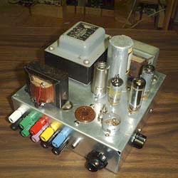
Figure 23 Schematic of My Own Design.
For a verbal description click here.
This was a project intended for those who were building my radio projects. It incorporates an audio amplifier and a power supply into the same compact chassis. The power supply circuit is essentially the same as figure 9. In the photo above the 6V6gt and 12AX7 audio amplifier tubes have been removed from their sockets. The transformer on the left front is the output transformer. The audio amplifier has enough gain to be used to amplify an electric guitar but would be more useful as a signal tracer. Full construction details are available at this location.
Conclusions.
It seems likely that a more compact and cooler running power supply could be made with silicon devices. The requirement for voltage measured in the hundreds of volts no longer eliminates this solution. BUT…THIS IS FUN WITH TUBES. I'm not going to tell you how to run your shop. You may build a power supply entirely of silicon devices if you like. You may use power tubes for the pass element and silicon devices as the reference and DC amplifier. Or you may go all tube. The choice is yours. I have tried to present the various options so you can make an intelligent choice. Good luck and above all have fun.