Storing Plywood and Other Sheet Goods.
At the lumber yard and home center plywood is stored horizontally. Because of this it generally arrives in your shop with little or no warp. What should you do with it. Storing it flat is out of the question unless you have one of those extravagant shops you read about in the magazines. If you lean it against a wall, which is unavoidable for most of us, you will wind up with warped plywood. Been there done that. But there is another way as you will see below.Selecting the Wall.
If you peaked you have seen how the sheets are clamped to the wall. But you can't use just any wall. If you place several thicknesses of plywood against an outside wall the temperature of the sheet next to the wall will be cooler in the winter and warmer in the summer than the temperature in the shop. In winter moisture will condense on the plywood and you may end up wishing you had just leaned the sheets against the wall where air could circulate behind them.You have to cut holes in the wall and stick clamps inside. This would not be a good thing to do to a wall that has insulation in it. So, an outside wall is out of the question.
The other important issue is strength of the wall. A wall covered with drywall or 3/16 inch thick paneling won't do either. You will most likely have to do what I did which is build a wall for this purpose. There is a storage area with shelves on the other side of my wall so it had to be strong. It is 1/2 inch plywood over 2 x 4 studs which are on 16 inch centers. The Sheets are held to the studs with screws rather than nails which might pull out.
The Clamps.
Here is a picture of the clamp I finally settled on. It is a Bessey clamp that is sold by Lowe's. The model number may be A8, 20, or TG4.012. Only aunt Bessey knows for sure.

The clamp in the photo is a bar clamp. The bar is 15 inches long and is horizontal in the picture. The fixed jaw of the clamp is on the left. The sliding jaw is approximately in the middle of the bar. The jaws are pointing upward. The fixed jaw has an elongated pad that begins two and one half inches from the bar and ends four and a half inches from the bar. The movable jaw has a large screw, more appropriately called a bolt, which is parallel to the bar. There is a red handle, for tightening, on the right end of the bolt. The left end of the bolt is fitted with a jaw pad which is circular and about one and a quarter inches in diameter. The center of the pad is about four inches from the bar. The total travel of the bolt is 2 and three fourths inches.I had to be sure the fixed jaw of the clamp would pass through the holes to the inside of the wall so I built a test wall out of some scraps.

The above picture is of a test wall made out of scraps. There are two pieces of plywood each about 10 by 12 inches. They are fastened together at their long edges by two short lengths of 2 by 4 that have their 4 dimension perpendicular to the plywood. There are two holes cut into one of the sheets, one is 3 inches in diameter and the other is 2 inches. These are the holes in which insertion of the clamps was tested.I had at first thought that a three inch hole would be needed for the clamps. The clamp went into the test wall, pictured above, so easily I decided to try a two inch hole. It still went in with ease but I decided not to push it any further.
WARNING!
A hole saw is a rather dangerous tool to use in a hand drill. When drilling into a wall there is no other alternative. A one half inch corded drill is required to power the saw. Such a drill has a great deal of torque. The saw can catch and cause the drill to twist unexpectedly. If you are holding it loosely or incorrectly you could get a sprained or even a broken wrist. Hold the two handles of the drill so twisting will push and/or pull on your forearms instead of twisting them.

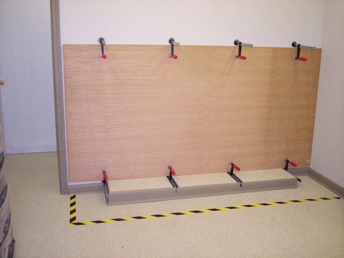
The above photo shows a section of wall with a door on the left and an inside corner on the right. The length of the wall is slightly over eight feet. There is base board and quarter round molding along the floor. There are four holes cut in the wall. The hole on the left is just above the base molding. Farther to the right the holes appear to be cut progressively lower until half of the hole on the right is cut through the molding. The holes are two feet apart and the hole on the right is centered one foot from the wall. A clamp is installed in the second hole from the left. It's fixed jaw is inside the wall and its sliding jaw outside. The clamp is tightened down with the jaws above the bar. In the foreground a corded electric drill is laying on the floor. There is a hole saw installed in the drill's chuck.It looks as if a line connecting the holes is not level. In fact it's the floor that isn't level due to settling of the building. The holes centers were marked using a laser level.
The edges of the plywood will not be supported by the clamps. Instead it will rest on the platforms shown in the picture below.

There are three platforms for the edges of the sheets to rest on. Each one is twenty-two inches wide and twelve inches deep.Note: Descriptions often use the terms width, length, height, and depth in a confusing manner. Part of the confusion is that there are four terms to describe three dimensions. In these pages I will stick with the convention that width is the left right dimension for the viewer, or imaginer, height is the up down dimension of the viewer, and depth is the dimension toward and away from the viewer. The word length will only be used for thin boards in which its meaning will be unambiguously understood.Each platform fits in one of the three gaps between the four holes. Each one is made up of a piece of plywood sitting on top of two 2 by 4s at each side. These 2 by 4s have their long dimension vertical. The height of the platforms brings their tops slightly above the centers of the holes.If the clamp bars were allowed to hold up the plywood sheets there would be the possibility of the bars denting the edges of the sheets. The edges of the sheets will rest on platforms as shown in the picture above. The 2 by 4s have been ripped so the tops of the platforms will be level rather than parallel to the floor. The holes are on twenty-four inch centers and are two inches in diameter. That leaves 22 inches between holes and this space is filled by the platforms.
Now to cut the upper holes and test the clamping.

In this picture, four more holes have been cut. The center of each hole in the top row is forty-nine inches above the center of the bottom hole. There are clamps in each of the holes. There is a piece of plywood held in two of the clamps. It is approximately eighteen inches wide and forty-eight inches high. It is held in the pair of clamps in the holes that are second from the left. The lower clamp has it's jaws above the bar and the upper clamp has its jaws below the bar. Thus the plywood is held firmly against the wall. All other clamps, upper and lower, are positioned with their jaws above the bar. This would make it possible to put another piece of plywood in place without interference from the upper clamp. Obviously, the lower clamp would have to be loosened first. After the plywood is in place and the lower clamp tightened the upper clamp can be loosened, rotated so its jaws are below the bar, and then tightened on the plywood.The piece of plywood is actually the four foot saw guide which is described elsewhere on this site. It has a slight warp in it and I was trying to straighten it.
Now for the real deal.
A full four by eight foot sheet of plywood is shown in the clamps. All upper clamps have their jaws below the bar and all lower clamps have their jaws above the bar. The bottom edge of the sheet is resting on the three platforms. The lower clamp bars are below the surface of the platforms so the sheet edge does not contact them. The platforms have been decorated to match the rest of the shop. Flooring tiles identical to those on the floor have been installed on the platforms. Baseboard and quarter round which is identical to that used at the base of all the walls has been placed around all three platforms. The clamp bars are a little longer than the depth of the platforms, therefore two notches have been cut in the baseboard so the bars of the clamps can extend through. Only the two clamps which fall between platforms require this treatment. The two end clamps are outside the baseboard.This piece of plywood has spent the previous two years leaning against a wall in the lawnmower house. It was subjected to summer temperature highs above 100 and winter lows well below freezing. It developed a considerable warp under these conditions. I hope it will flatten out over time from being clamped flat like this.

The picture above was taken by Sue which probably accounts for the rather unflattering view of my posterior. I am installing the lumber storage part of my wood storage wall.This picture shows me with my back to the camera installing lumber racks on the wall above the plywood storage area. The sheet of plywood has been removed and the upper row of clamps have been used to mount a temporary ledger board to align the individual racks. Each rack is a sandwich of 3/4 inch plywood. The bread of the sandwich consists of two vertical pieces of plywood that are thirty inches high and four inches in depth. The meet is three horizontal pieces which jut out from the wall by 14 inches and are held between the vertical pieces. The upper surface of each wedge shaped piece is flat while the lower edge is angled. Between the horizontal pieces and above the top one and sandwiched between the vertical pieces are 3/4 by 1 inch strips of poplar. The head of a screw which passes through one of these strips and into a wall stud is visible just above my head. The pictures shows three racks installed. I am shown mounting a fourth and a fifth one will be installed when I am finished.
Here is a dimensioned drawing of the lumber rack. This idea is not original with me. It comes from the Woodsmith Shop TV show and website. I have altered the dimensions to suit my needs.

This is a line drawing representing a side view of one of the racks. Parts which are between the two vertical pieces are shown in dashed lines. The two vertical pieces look like one in the drawing because one is directly behind the other in the drawing. The two vertical members are 30 inches high and 4 inches wide. The three horizontal pieces are 14 inches wide, 4 inches high at the left side, and 2 inches high at the right side. The shape of one of these goes as follows. Starting at the lower left corner and moving clockwise. The line goes up 4 inches. Then it turns to the right and goes horizontally for 14 inches. Then it turns down and goes for 2 inches. At this point it turns on the angled part. It goes down and to the left on a slope of 1 to 5 or 11.3 degrees. At the end of this run it has descended 2 inches and moved to the left by 10 inches. It then turns horizontal again and goes 4 inches to the left. This brings us back to the starting point. There are three of these. The first has its top located 4 inches above the bottom end of the vertical members which places its bottom even with the bottoms of the vertical members. The second has its top 14 inches above the bottom and the third has its top 24 inches above the bottom. Above each horizontal member is a piece of poplar which is 6 inches long and approximately 1 inch wide. This is not critical. The poplar pieces are placed so their left edges are even with the left edges of the vertical members.All pieces are nominally 3/4 inches thick which is actually 23/32 of an inch. The poplar strips must be ripped or planed to be the same thickness as the plywood.
The racks are put together with 2 inch number 8 woodscrews. No glue is used. Everything is laid out and clamped on the workbench and holes for the screws are predrilled. Four screws are put into each horizontal piece and two into each poplar strip. Then the whole thing is unclamped, turned over, and reclamped. Another set of screws is put into each piece being careful not to run into the screws coming from the other side.
Screws have to go through the poplar strips into the wall studs. Be careful to leave enough room for them. These screws will be going cross grain. The heads of woodscrews can act as wedges and split the wood. I recommend using pan head screws with washers or washer head screws. The longer the better.
The picture below shows the completed storage area loaded up.
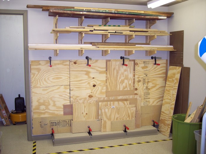
Both the upper rack and sheet goods storage have been loaded up with wood that has been in the lawnmower house for several years. Sue is glad to have it gone. She finds it easier to park the riding lawnmower now.That full sheet of plywood is against the wall and a number of partial sheets have been placed in front of it. Each layer must be all the same thickness so nothing will be forced into a warp. Some smaller pieces are held in the bottom clamps only.
I tested the lumber rack by doing a pull up on one of the horizontal pieces. Nothing showed a sign of coming apart. With 5 such racks to hold everything I doubt if there is enough physical space to allow overloading of the rack.
THE END.
Back to Woodworking Projects Page.
This page last updated October 27, 2009.