For a verbal description click here.
A 200 watt,
One night I was tuning around on 75 meters with my Drake 2B. Just a little below 3900 kc I heard a carrier beat and then another. I switched over to AM mode and sure enough there were a total of 4 AM QSOs going on. They weren't all retreads like me either. Some of them were young guys who had found a more relaxing way to communicate. Just as young musicians are embracing tube amplifiers, a few young hams are not only holding on to tubes but the mode of transmission they are most closely associated with.
80 through 10 meter,
AM Ham Transmitter.On a whim I logged onto eBay and typed "modulation transformer" into the search box. To my utter surprise I got a couple of hits. One was the modulation transformer from a Viking Valiant. Checking the seller's other auctions netted the plate transformer and filter choke from the same rig. I bid on, and won them. Wow!
When I first got on AM and before I became interested in SSB I heard a lot of different transmitters on the air. The one I was in love with and always wanted was the Valiant. Instead I built a pair of 813s modulated by a pair of 810s. Then the move to SSB (Scientific Set Back) began. Although I went with the flow I always missed the clear sound of AM. Well, transistors and SSB be damned. I'm going back to a tube AM transmitter.
Keep watching this page. I will update it as the project goes forward or experiences set backs which ever way it goes.
Max K4ODS
The modulator.
Although I found some of the transformers one I didn't have any luck finding was the driver transformer. I bought a few on eBay but they turned out to be the wrong turns ratio or too big. In an article elsewhere on this site I have discussed classes of amplifiers and in the AB2 section I stated that "You need a transformer to drive an AB2 amplifier. See Class AB2 and Transformer Coupling. Use your back button to return here.About 10 months after posting this page I received an email from a gentleman in Indonesia who suggested using direct coupled cathode followers to drive AB2 outputs. About 10 months after the email I finally found the time to breadboard up a circuit to test the suggestion. It works. Here is the circuit.
For a verbal description click here.
Not everything is finalized and at this writing there is a funny little oscillation on the negative peak of the output. I think it's caused by a ground loop.
Eventually I plan to add negative feedback to clean up some cross over distortion. I have to solve that oscillation problem first. Also I haven't set the final values for the coupling caps. Before adding negative feedback I need to compensate the amp at low and high ends. That will change the coupling cap values and cause the addition of an RC network somewhere in the circuit.
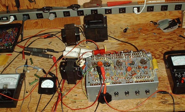
The oscillation seems to be caused by so much of the circuit being scattered out across the workbench with nothing shielded or grounded. I could just wave my scope probe in the air anywhere around and over the setup and pick it up. I'm going to have to build it on the final chassis and do some of the fine tuning after it is built. I did some scaling of the photos in the Valiant instruction manual and it appears that it was built on a 17 by 13 by 4 inch chassis. I'm pretty sure I have one in the attic. I was planning to use it to build a kW linear amplifier for which I have virtually all the parts. I may never build that project so I'd rather use it for this one.
Well, that's where things stand on April 25, 2004. I'm going to give the Valiant a rest while I get back to the dedicated headphone amplifier for which the parts have come in.
Keep checking back.
C U L
Max
K 4 O D S
Home
This page last updated April 25, 2004.