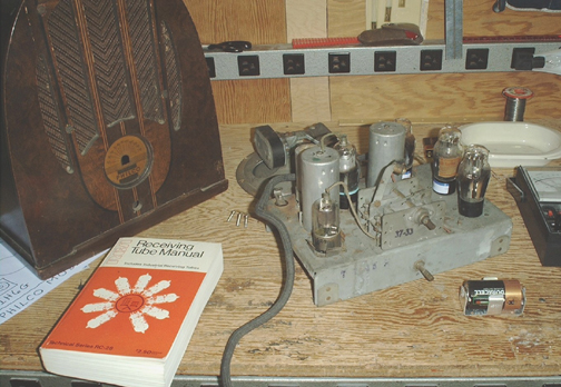
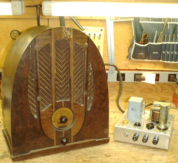
I found this Philco radio at an antique mall. It had dust, dirt, spider webs and even a dead spider in it. I have traced out the circuit and restored it to operation.
Circuit of the Philco Radio.
The inspection tag on this radio is dated November 26, 1937. The signal path is not unlike the standard "all American five" (tubes) which was the peak of cheep radios until the "all Japanese six" (transistors) came out in the sixties. The only thing missing is the built-in loop antenna.There are two unique features of this radio. One is the push-pull audio output. The filament type tubes precluded the use of a phase splitter and negative feedback was not used in consumer electronics in 1937. The signal on pin 4 (grid) of the 1E7 is attenuated by the reciprocal of the gain of the 1H4 stage. This inverts the signal and provides an overall unity gain. This open-loop method provides surprisingly well balanced drive to the two grids of the 1E7.
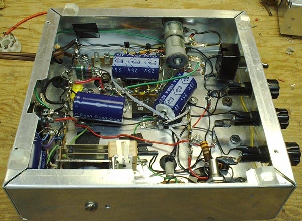
The other unique feature is the use of a high impedance speaker instead of an output transformer and low impedance speaker is in most other radios I have seen. The coil does not ride on the speaker cone as with low impedance voice coils but is mounted on the frame. An arrangement of levers which is mostly obscured by the coil transfers the motion of something inside the coil to the speaker cone.
If you ever get your hands on a radio like this you will find things under the chassis which look like 3-lug terminal strips. There is a capacitor built into these units connected between the end lugs leaving the center lug for a tie point. The two capacitors coupling into the 1E7 were leaky. Rather than try to remove these combination terminal strips/capacitors I left them in place, added a 1 lug terminal strip and put the new capacitor in series with the old one. Yes I remembered to move the plate load resistor to the new tie point.
The power cable told an interesting story. It had a 7-pin plug on the end and two wires with ragged stripped ends emerging from the jacket about half a foot above the plug. These two wires led to the 2-volt filaments. They must have been using a single led-acid cell. The filaments need almost half an amp. I have seen these led-acid cells in clear plastic cases with three colored (red, yellow and green) gravity balls to indicate the charge condition of the cell. The 7-pin plug would have connected to a B-C pack of dry batteries. Before you start wondering if the plug might have been to a vibrator supply I must state that there was absolutely no connection between the filament wires and the 7-pin plug except for ground. If the vibrator pack had possessed its own set of wires to the led-acid cell the on-off switch on the radio would not have shut down the vibrator supply. As originally connected the on-off switch on the radio opened the filament supply and removed a resistor load on one of the bias supplies. This load was likely there so all of the parts of the B-C pack would run down about the same time.
You may be wondering how I arrived at the voltages I am using. I used three different transistor supplies to juice up the filaments and bias potentials. I looked up the output tube (1E7) in a tube manual and found several conditions for push-pull operation. I set the output tube's bias to 7.5 volts and the AGC bias to about 5 volts. I tied the two B+ connections together and put them on an adjustable regulated tube power supply. I started about 90 volts and eased it up until the oscillator didn't drop out at the low end of the AM band. The can-type filter capacitor which is on the screen grid supply line is rated at 150 volts. The tube manual ratings for the 1E7 gave 130 volts plate and screen and -7.5 for grid bias so that seemed like a good place to stop. While playing with the output bias I discovered the leaky coupling capacitors and after "replacing" them I found that the operating point specified in the tube manual gave the best performance. Twiddling the AGC bias gave best performance at 4.5 volts.
All-in-all it works pretty well. It's not as hot as more recent tube radios but it will get more distant stations at night than a transistor radio. The planetary tuning drive slips a little and the pointer broke when I tried to remove it from the shaft. I think I can make a new one.
For a verbal description click here.
If you should happen to get hold of a schematic diagram of this radio you will notice some differences between it and the diagram above. The power socket has been rewired to work with the power supply rather than the original B-C battery pack.
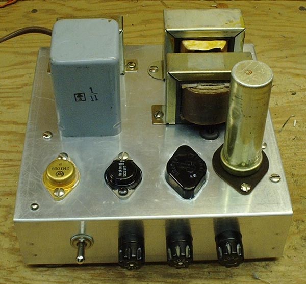
Power Supply for the Philco Radio
If you try to duplicate this power supply part for part you are doomed to failure. The reason is I built it from parts I had on hand. Some of them I have had for thirty years. If you are really serious about building one similar to it you will have to do a lot a parts substitution.Why things are.
There are four sources of EMF in this power supply.The B+ supply uses a shunt zener diode regulator for simplicity. The units used are nominally 60 volt 50 watt units. Nothing like this is manufactured today. Even if you could find them they would likely cost an arm and a leg. Here is a circuit which will duplicate a high power zener diode (and is probably the reason why high power zeners are no longer available).
- 130 VDC (regulated) @ 25 mA B+
- -2 VDC (regulated) @ 0.5 A Filament
- -7.5 VDC @ 0 mA Output bias C - 1
- -4.5 VDC @ 0 mA AGC bias C - 2
Circuit A would be the one to use if you have a transistor rated at 150 volts or higher and a single 130 volt low power zener. If you don't have, and can't find, a single zener with that much voltage then circuit B is for you. You may stack as many zeners as you need to. If you already have a couple of 100 volt or 3 60 volt transistors then use circuit C. You can stack as many transistor-zener combinations as you need. Don't forget that each silicon transistor will add about 0.65 volts to the voltage of the low-power zener diode. 
For a verbal description click here.
If your really into tubes you can design a regulator using a series pass tube. I didn't do that because I didn't want the power supply to be bigger than the radio.
The can of the large capacitor is not electrically hot. I used an insulator to avoid creating a ground-loop which would be carrying large pulsed currents from charging the capacitor.
In the case of the transformers I used what I had. Placing two filament transformers secondary-to-secondary is quite an old trick to get 120 VAC isolated from the line. I used to have a transformer with 120 VAC @ 50 mA and a 6.3 @ 2A secondaries. I must have used it in another project. If you have or can find one you will only need one more transformer to complete this power supply.
The filament supply is critical. I would hate to have to design a tube based regulator the provide this voltage. These tubes are rather delicate. Long term operation with too little voltage can permanently reduce the ability of the filaments to emit electrons. Too much voltage can do the same thing only much quicker. A shunt transistor regulator is a must because the common failure mode of a transistor is shorted. A failed series regulator could shoot 5 or 6 volts to the filaments and bye the time your ears detected a change in the radio's performance it would be too late, the tubes would already be shot. The circuit is such that if either the power or the driver transistor fails the filament voltage will go to nearly zero and the radio will go silent alerting you to trouble. As with the zener diodes the TO3 power transistor is one I just happened to have. A 2N3055 should work nicely but because of the low operating voltage almost any TO3 NPN transistor should work here.
You may think of the on-off relay as over-kill but I wanted the option of hiding the power supply and having the radio perform exactly as it did in 1937. Once again the relay driver transistor is a higher voltage unit than is required. It's a TO220 but it doesn't need any heat sink. The on/off switch on the power supply energizes only the power supply for the relay circuit. When the switch on the radio is turned on the relay will close energizing the A B and C supplies to operate the radio.
General construction
I didn't use a printed circuit board for the transistor circuit. If you look at the photograph of the power supply's under-side you can see the two 2N3904s on terminal strips at the top of the picture just above the large capacitor. I think this is a nice retro touch for a 67 year old radio. The power is fed to the radio through an Octal socket on the power supply and an octal plug on the end of the radio's power cable. The original plug was a 7-pin (like some of the tubes of that era) but I didn't have a matching socket.
For a verbal description click here.
The radio works rather well considering its age. Unfortunately its cabinet is not in prime shape. I don't know if a skilled wood refinisher could do much with it. That considerably reduces its value but I didn't buy it to make money. I enjoy taking these old radios that everyone else has given up on and restoring them to operation.
This site begun March 14, 2001This page last updated March 16, 2004.