Chasing DX late at night on the AM radio band can be a lot of fun but if you get serious enough about it to start logging station calls and times you will also want to log the frequency. The dial calibration on AA5s is not even close enough to be sure what 100 kc segment you are in. Even those early high fidelity AM tuners didn't have Collins-like calibration. If you are lucky enough to have an R-390 or something similar, fine. If you aren't so endowed, read on.
There are those tuners and receivers with digital frequency readout but they are all solid state. SS tuners were designed primarily for FM stereo and the AM section was added as an afterthought and the circuit received little or no attention from top notch receiver designers. An AA5 will easily outperform these poor tuner circuits and an AA6 will surpass even a well designed SS AM tuner circuit.
The Phase Locked Loop (PLL) Frequency Synthesizer Circuit.
A digital frequency synthesizer probably could be implemented with only about 100 vacuum tubes. After all, early computer designers used thousands of tubes in those pioneering machines. I doubt if most of you are interested in building such a device and installing the extra window mounted air conditioner that would be required to keep it cool.I have operated an analog frequency synthesizer that would be doable with a few tubes but that's a project for my second retirement. It suffered from a lot of spurious signals and might not be satisfactory for an AM broadcast receiver.
Yes, it's solid state. You can buy the kit from Ocean State Electronics. Part number 80-1401. At $89.88 it isn't cheap but if you don't spend money on a hobby, you're not really serious about it. I attempted to second source the chips and maybe save you some money but no luck. The reason is, the 28 pin chip on the display and keypad board is a PCI60C57C programmable controller. If you, or I, were to go out and buy one, and we could, it wouldn't be programmed to do what it does in this device.
There is also a little 8 pin DIP which has the number 24LC018 or maybe it's 24LC01B. A Google search did turn up both numbers and a lot of people willing to sell them to me. But I couldn't find any data. It's kind of mysterious. 5 of the 8 pins are grounded and a 6th is connected to Vcc. That only leaves 2 pins to converse with the PCI. I have no idea what it does.
Building the Kit.
Don't just willy-nilly start construction. You won't be using one of the supplied boards. Also I have a few suggestions that deviate from the steps in the instruction pamphlet, such as they are. The kit comes in a transparent plastic box with a snap-down lid. Inside you will find two plastic wrapped packages. Open the one that says "Phase-Locked-Loop Controller Board for MC145170". This package contains the programmable controller IC and the LCD readout.Before You Solder Anything.
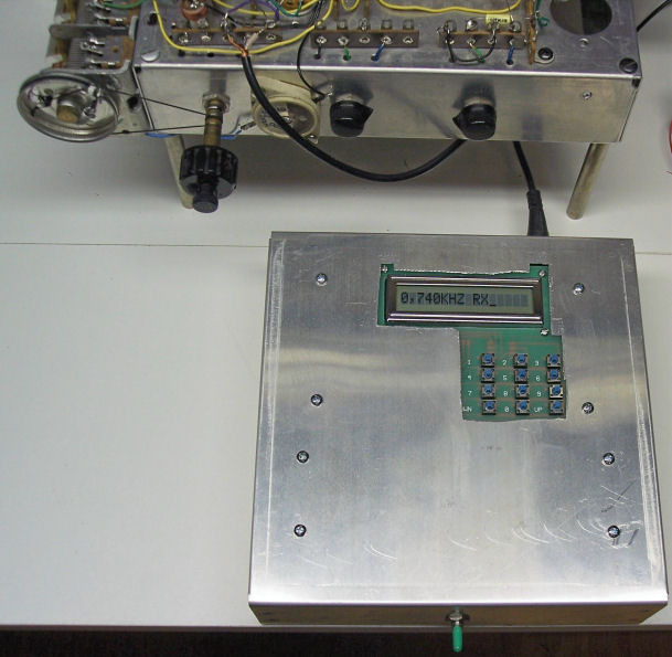
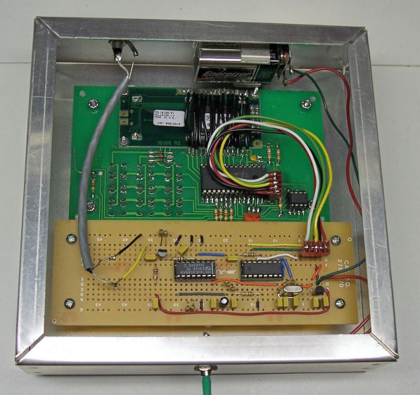
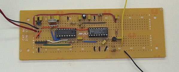
As you can see from the photos above and below I built the entire thing into a 7x7x2 inch chassis because I had one on hand. The usual suspects don't seem to have anything comparable. I'm sure you couldn't squeeze it into a 7x5x2 and the next step up is a 10x6x2. Oh well, do what ever works for you.The Voltage Controlled Oscillator will not be built on the board provided but on a prototyping board which is better for the purpose. The board provided has a lot of wasted space. The proto boards which I have used in this and other projects on the site are also available from Ocean State Electronics as part number 22-508 price $7.60. Place the virgin boards on top of the chassis, mark, and drill the mounting holes. The display and keypad board will mount flat against the chassis from the inside and the VCO board will mount on 4 standoffs supplied in the kit.
Don't start soldering yet. Look at the display board and see how it fits into the cutout in the dis'key (a contraction of display and keypad) board. The kit supplier recommends using glue, not included, but I don't like that. It seems that glue is either too permanent or not permanent enough.The display mounts from the back of the dis'key board with the row of gold plated connection points at the top. Note there are 4 mounting holes in the display board. If you were to drill a hole at the lower left corner, as viewed from the front, a trace would be cut. So don't drill that one. Do drill the other three with a 7/64 inch bit. When the time comes to mount the display you can fasten it in place so it will stay together but you can still take it apart if you ever need or want to.
Here is the schematic diagram of what you will be building.
For a verbal description click here
Now you can start construction. Right off you will encounter a zero ohm resistor. How's that again?A zero ohm resistor is more commonly known as a piece of wire. However the machinery that assembles circuit boards automatically is unable to handle a simple piece of wire. It has been made to pick up resistors and put them in place. So when board designers need a jumper they use a zero ohm resistor instead of a piece of wire.
You may want to keep the zero ohm resistor to show as an example of the ridiculous times we live in and use a piece of wire instead. The zero ohm resistor is a little too long for the spacing of the pads so wire would probably be better. Be careful not to short out the traces that are being bridged by the ZOR.
Oh, did I mention? This is a surface mount board. But don't be scared off by this. If I can do it so can you. Go ahead and mount everything EXCEPT.
After mounting everything except those things listed above it is time to mount the little 5 pin plug. It is a through-hole mount but it represents a bit of a headache. Push the pins through the plug header (that's the little plastic strip that holds the pins) until most of each pin sticks out on the board side of the header. The plug side is flat. Make sure all pins are lined up perfectly. Push the pins into the 5 holes where the plug goes making sure the board side of the header is toward the board. Set the board face down on a hard flat surface such as the top of a new chassis. This will push the pins back through the board and make them flush with the surface. Hold the plug perpendicular to the board with one finger while holding the solder in two other fingers. Solder one of the pins to the foil on the board. Be sure to solder a pin your finger is not touching. (This three-handed procedure is well known to experienced solderers.) Check the front of the board to make sure the pins are indeed flush with the surface. If all is well go back and solder the remaining 4 pins. BE CAREFUL NOT TO FLOW SOLDER VERY FAR UP THE PINS. After soldering is complete and all pins have cooled, push the header down as far as it will go.
- The 5 pin plug.
- The 8 pin DIP socket.
- The 4.7 k ohm resistor next to it.
- The display board.
- The keypad switches.
Now install the resistor and 8 pin dip socket.
This is a good point to check for any poorly soldered connections or solder bridges. If any such soldering errors are found, correct them before proceeding.
You don't need to mount the switch, not supplied, to change between receive and transmit. Use a jumper wire to permanently wire it for receive operation.
Mount the display with three 4-40x3/8 screws and matching nuts. Then wire the connections as directed.
Mount the 12 switches in the keypad locations as instructed.
Give the board one last inspection for unsoldered connections or solder bridges. Do not install the ICs in their sockets just yet. All in good time.
Now we come to those plugs. They don't really tell you how to put the wires into them. The extremely meager instructions imply that you just stick them in and they are supposed to stay. Well, they don't. I was afraid that using the soldering iron would melt the plastic but to my surprise it didn't. Strip and tin the ends of the wires, stick them into the plugs from the side as indicated in the picture in the supplied instructions, and then solder them in place.
Set the dis'key board aside until it is needed.
VCO Board Construction.
Open the other package of parts. Put the included board wherever you keep things you don't want to throw away but doubt if you will ever use again. In both kits I bought they included one 16 pin IC socket and one 14 pin. They should have sent two 16 pin sockets. Maybe you will be luckier than I was. If not, you will have to do what I did which was to take a socket from stock. They also failed to supply .1 microfarad capacitors, substituting .01s in their place.Sort out the following parts and put the leftovers in your spare parts storage space.
- MC145170 IC.
- 74HC4046 IC.
- 78L05, looks like a transistor.
- 1 or 2 16 pin DIP IC sockets.
- 10 Mc crystal.
- 5 pin plug.
- 1 uf electrolytic capacitor.
- 10 k ohm resistor.
- 68 k ohm resistor.
- 2 100 k ohm resistors.
- 470 k ohm resistor.
- 4 metal standoffs.
Here is a list of the things you will need to supply.
- 16 pin IC socket, maybe.
- 2N3904 transistor.
- 100 ohm resistor.
- 390 ohm resistor.
- 2 1 k ohm resistors.
- 47 k ohm resistor.
- 2 27 pf capacitors.
- 560 pf capacitor.
- 8 0.1 uf capacitors.
- Prototyping board, OSE # 22-508 price $7.60.
- 9 volt battery.
- Battery holder with snap-on connections.
- On-Off switch.
- RCA Phono jack.
- RCA Phono plug to pigtail ends. For connection to radio.
- Chassis of your choice.
- Miscellaneous screws, wire, and solder.
Here is the schematic followed by the layout of the prototyping board.
For a verbal description click here.
I corrected one sin of omission committed by the kit designer. The 4046 uses two frequency determining resistors, one to pin 11 and the other to pin 12. The one to pin 11 sets the maximum frequency in conjunction with the capacitor connected between pins 6 and 7. The resistor to pin 12 sets the minimum frequency. If this resistor is omitted the minimum frequency is zero. The practical effect of this is to stop the oscillator if the loop commands a low frequency. The only way to recover from this is to key in an impossibly high frequency such as 500 Mc. The oscillator will restart at the highest frequency it can manage. Then you can work your way back down as long as you don't go too low. The correction for this is to connect a resistor from pin 12 to ground. There was no trace provided for this on the supplied board. There's another reason for using a different board.Construction Notes.
Although the pins of the 5 pin plug are flush with the surface of the diskey board they could be shorted out by contact with the metal chassis. You should place some insulating material such as vinyl tape or fish paper over that spot to prevent shorts.The only method I know of to make irregular shaped holes in a chassis is a nibbling tool. The only thing to be said in its favor is it works. If you have another method by all means use it. You might even want to share your knowledge with us.
Connecting the PLL to an AM radio.
You need to disable the oscillator but keep the tuned circuit to filter the square wave output of the VCO into a sine wave.The usual AM radio converter uses a Hartley oscillator circuit. Disconnect the wire from the cathode of the converter tube and connect it to the grounded end of the oscillator coil. Connect the shield of the cable from the PLL circuit to this ground point. Connect the inner conductor to the tap on the coil where the cathode used to be connected. Try to limit the length of this shielded cable to 1 foot, certainly no more than 2 feet. Here is the schematic diagram.
For a verbal description click here.
Other oscillator circuits may present special problems. If you can't figure it out drop me an email with your circuit attached and I'll be glad to help you.Operation.
Setting the IF Offset.
In receive mode the oscillator is not set to the frequency which is displayed but the oscillator is offset by the amount of the intermediate frequency (IF). This offset may be positive, oscillator above the received frequency, or negative, oscillator below the received frequency. To set the IF offset to positive 455 kc do the following.
- Press the 8 key.
- The display will show "IF + _"
- Press 0, 0, 4, 5, 5.
- The display will show "IF +0,455KHZ"
- Press the 9 key.
- The display will show a random number "X,XXX KHZ RX_"
- To program a frequency such as 650 kc
Press 0, 0, 0, 6, 5, 0.- The display will now show "0,650KHZ RX_"
- To display the IF offset without changing it press the 9 key.
Press the 9 key again to return to the received frequency display.To program a negative offset press the 6 or 7 key instead of the 8 key and perform steps 2 through 5 above except key the numbers corresponding to the IF of your particular receiver.
The values of the IF offset and the last frequency keyed in will not be lost when power is turned off.
Tuning in a station.
The programmable controller used in this kit is apparently capable of setting up frequencies in excess of 100 Mc. However the oscillator described in this article will not come anywhere near that. Never the less you still have to key in all those leading zeros to get the frequency you want. For example, to tune to 1530 kc you must key in 0,0,1,5,3,0. The display will show "1,530KHZ RX_". When ever the display ends in "RX_" you may key in another frequency.
- Key in the frequency of the station you want to hear.
- Tune the radio dial to that frequency.
- Make small adjustments in the radio tuning for best (usually loudest) sound.
- Listen and enjoy.
If you want to surf the band the best way may be to use the up and down keys. Each press of these keys moves the frequency up or down 1 kc. You may find it quicker to press one of these keys 10 times rather than keying in the new frequency each time. Remember to tune the radio dial every two or three channels to keep up with the oscillator frequency.
Oh yes, in the rest of the world AM radio uses 9 kc spacing. You only need to press the button 9 times instead of 10. Is that stating the obvious?
A radio really isn't working unless it glows in the dark.
This page last updated July 23, 2006.