For a verbal description click here.
If after reducing the oscillator amplitude, disabling the meter, disabling the square-wave generator, and improving the power supply, the distortion reading is still too high you need to do some work on the oscillator circuit.
How the Oscillator Works.
When most people think of a lamp stabilized oscillator they think of the Wean bridge circuit. That circuit was used exclusively by Hewlett-Packard probably because of patents they held. There are other methods of making an RC (resistance capacitance) oscillator that uses a tungsten lamp to stabilize its output voltage.In the theoretical analysis of an oscillator if the gain is higher than needed to maintain oscillation, the amplitude keeps building up forever. In practical circuits the amplitude stops building up when the tube, transistor, op amp, or what ever, begins to saturate. Saturation also means distortion. If we want a low distortion oscillator we must prevent the amplifying device from going into saturation.
Again, theoretically, if you set the gain of the amplifying device just right the amplitude of oscillation will neither build up or decay. In a mathematical problem you can set the gain of an amplifier to what ever you need and to as many significant digits as required and it will not change. So, you can always get the gain the circuit needs. Note: if the gain is lower than required the oscillations are started by the turn-on transient but eventually decay to zero.
If you set up an oscillator circuit that has a pot to adjust the amount of gain, and I have, you can see the amplitude building up when the gain is higher than needed and decay when the gain is low. If you set the pot j-u-s-t r-i-g-h-t you can get the oscillator to work at a level below saturation and it will produce an almost pure sine wave. But it won't stay that way very long as tube or transistor parameters drift and the gain changes from that perfect value.
The problem is, of course, getting that Goldilocks gain and keeping it constant at the required value. The tungsten lamp is excellent for this because its resistance increases as its temperature increases and its temperature increases as the current flowing through it increases. Thus we have a current controlled resistor. A simplified version of the oscillator used in the IG-18 is shown below.
For a verbal description click here.
The bridged-T circuit, consisting of two resistors and two capacitors, produces a slight dip in amplitude at a frequency determined by the component values. It's by no stretch of the imagination a notch filter like the twin-T, it's just a modest dip but it's enough.
In the circuit above there are two feedback paths, one positive, the lamp, and the other negative, the bridged-T circuit. At high and low frequencies the negative feedback through the bridged-T circuit cancels the effect of positive feedback through the lamp. At the frequency where the bridged-T circuit produces its dip the positive feedback through the lamp predominates and causes oscillation.
If the amplitude increases the lamp will get hotter, its resistance will increase and the amount of positive feedback will be reduced, counteracting the change. If the amplitude falls the lamp cools a little lowering its resistance and increasing the amount of positive feedback again counteracting the change. Thus the amplitude of oscillation is maintained at a constant value without depending on amplifier saturation. The lamp corrects automatically for changes in the parameters of the amplifying devices inside the amplifier block. The initial amplitude is set by setting the value of the resistor from the noninverting input to ground.
In older vacuum tube oscillators that used a 3 watt lamp the glow of the filament was faintly visible if viewed in a dark room. The lamp used in the IG-18 is such a low wattage its glow is not visible when the oscillator is operating normally.
The Problem.
The cause of the distortion in the amplifier is Q3 and its load. The load for Q3 is the two diodes D1 and D2 and the 10 k ohm resistor R12. The voltage at the collector of Q3 swings over a range in excess of 28 volts peak-to-peak when the output amplitude is 10 volts RMS. This causes a very large current swing in R12 and the two diodes. The distortion comes from the diodes and the base-emitter junctions of Q4 and Q5.The Solution.
The best solution to this problem is to use a constant current sink in place of R12. This current sink can be made of Q6 which is part of the no-longer needed Schmitt trigger. A transistor is already a natural current sink. If the base voltage is held firmly by a low resistance voltage divider the current is set by the value of the emitter resistor and it becomes a nearly perfect current sink over the normal voltage range of the transistor.The Modification.
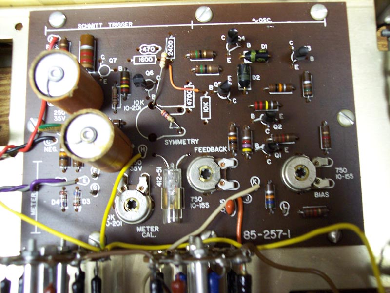
Refer to the circuit board drawing and photo below. Keep in mind that the drawing is from the bottom while the photo is from the top.

Measure the distortion again. Still not low enough?
- Remove the following components from the main circuit board.
- R16, Symmetry pot.
- Q7
- R12
- R15
- R17
- R18
- R19
- C7
- Install a 1,000 ohm resistor in the former home of R18.
- Install a 2,700 ohm resistor between the large hole near the letter "B" where the symmetry pot used to be and the small hole near the word "symmetry". At the large hole bend the resistor lead over against the foil but do not solder it yet. Solder the other end.
- Install a 43 k ohm resistor between the large hole near the letter "B" and the hole closest to the back of the board where R17 used to be. Solder both ends.
- Install a piece of hookup wire from the front hole of R17 to the back hole of R12. Solder both ends.
- Introduction and Modifications 1, 2, and 3.
- Modification 4, Power Supply Regulator.
- Modification 5, Decreasing Distortion in Amplifier. (You are here.)
- Modification 6, Mounting Power Transformer Outside the Case.
The day that the Heath company closed its doors
was a sad day indeed for electronics home brewers.
Before it existed there was nothing in the world like it,
It was never equaled by its wood-be competition,
And there will never again be anything like it.
HomeOr use your "Back" button to return to where you were.
This page last updated April 15, 2006.