I have recently had several exchanges of emails with someone outside of north America who completed this project. He reports that the meter is now functioning but not without a few problems, most of which were caused by me. Based on this experience I have made a number of changes to the text and the schematic diagram. The beginning of the construction section will list the changes.There is one more piece of test equipment we need before we can start having fun with tubes. If you grew up on transistors you may not even know what a filter choke is. It's a big inductor, physically as well as electrically.
The familiar transistor power supply has one big mother of a filter capacitor on the rectifier output followed by an electronic regulator which regulates out all voltage variations including ripple. In vacuum tube days only the very tip top of the line test equipment (Hewlett Packard, Tektronics, General Radio, etc) used electronic regulators. So it was necessary to find a way to filter out most of the ripple using passive components (not tubes). In many devices such as low cost radios and phonographs the designers managed to use resistor-capacitor RC filters but if the current drawn by the circuit was large and the application demanding, such as a Hi-fi power amplifier, the power supply needed an inductor-capacitor (LC) filter.
An inductor needs to have many turns of wire wound on an iron core. The wire must be heavy enough to have a low enough resistance so it can conduct the direct current without dissipating an excessive, usually five watts or less, amount of power. The core had to have enough iron in it so as not to saturate at the maximum specified current. Filter chokes are getting hard to find they mostly are seen at electronic flea markets (hamfests) and from dealers on the net who specialize in antique electronic parts. If you're a retread like me you may have some stored in your basement or garage. It is very likely these old chokes whether in your garage or from a flea market won't be marked with specifications. Don't despair. Ve have vays of finding out zese sings.
Now that I have created a need I am prepared to fill it. I designed the Filter Choke Analyzer to test the closet full (not quite) of old chokes I have.
How it Works
It's not enough to just measure the inductance of a choke. You need to know how it behaves when carrying a mixture of AC and DC. The simplified circuit is shown here.
For a verbal description click here.
The transformer isolates the test circuit from the line and provides some step down. The secondary delivers very little Alternating Current but it must be capable of passing the DC without overloading the winding or saturating the transformer's core. The value in amps of the alternating current can be found by dividing the voltage across the resistor by the resistance of the resistor. In this example that's pretty easy. Next the reactance of the inductor can be found by dividing the alternating voltage by the AC. After the reactance is known the inductance can be calculated from the formula
L = XL/( 2 Pi f )
where XL is the inductive reactance and f is the line frequency of 60 Hz (50 outside U S and Canada). When the DC power supply is turned up from zero the inductor's core will begin to saturate, the inductance will be decreased, as will the reactance and the AC will rise. The new value of inductance can be determined by repeating the calculation.
The AC voltmeters are not phase sensitive. As you know the current lags the voltage by 90 degrees in an inductive circuit. In a true inductance meter the meter which reads the current should only respond to current which is 90 degrees out of phase with the applied voltage. Some inductors have a small reactance to resistance ratio or Q. A filter choke, by definition, has a relatively high Q even at 60 cycles although they are intended to operate at 120 cycles. This meter doesn't know the difference between inductance and resistance but it makes no difference as long as it is used as intended. This fact is used to calibrate the instrument. Both AC voltmeters must not respond to DC.
The DC is necessary to partially saturate the filter choke's core so the test is realistic. The variable source of 0 to 120 VAC comes from a variable transformer. Many people call these devices Variacs or Powerstats. Both of these are trade mark names. The generic name is variable transformer. This tester can't be built without one. It might be possible to use a hi wattage potentiometer but it would turn a lot of electrical energy into heat.
If you don't have a DC power supply with a built-in current meter you will need to include a DC current meter in your Filter Choke Tester. You might even want to go so far as to build in the whole DC power supply. I didn't because I already have one.
The Circuit
The schematic diagram of the analyzer is shown here.
For a verbal description click here.
ALERT
The voltage range switch must be a break before make switch. That means as you slowly turn the switch from one position to the next the moving contact must break contact with the stationary contact it is leaving BEFORE making contact with the stationary contact it is going to. A make before break switch will short something on almost every change and blow fuses.I have just found a mistake in the schematic above. It is fixed now but if you are trying to build this project and this notice is new to you, you have the old version. The mistake concerns the pot below the meter and bridge rectifier.
End of alert.
The transformer which provides + and - 12 volts for the op amps is a 24 VCT at 1 amp and the one which energizes the test circuit is 40 VCT at 1 amp.The voltage range switch makes it possible to accurately set low voltages, less than one volt, on the test circuit. The switch is shown in the 0 to 40 volt position. The 0 to 20 volt position uses the center-tap of the 40 VCT transformer. Then the input of the Variac, er, the variable transformer is disconnected from the line and connected to the 24 volt source from the other transformer. In the lowest voltage setting the variable transformer is energized from 12 volts from the 24 VCT transformer and the test circuit is energized from one end and the center tap of the 40 VCT thinggy.
The calibration has been set to 1 volt = 1 henry. This requires that the alternating current through the unknown inductor be 2.6526 mA for 60 cycles (3.1831 mA for 50 cycles). That's not likely to overload a 1 amp transformer is it? But remember that the transformer secondary winding and the resistor must carry the DC as well. The AC when passed through the 1.00 ohm resistor produces a voltage drop of 2.6526 mV for 60 cycles (3.1831 mV for 50 cycles). This voltage is amplified by one half of a TLO72 op amp which has a gain of 92.248 for 60 cycles (78.540 for 50 cycles) (or as close as you can come to that) which brings it up to .25 volts. When the range switch is in the SET position this .25 volts is fed to the AC voltmeter circuit. The circuit produces a full-scale reading with .5 volts AC applied to its input. The variable transformer and the voltage range switch are adjusted in concert until the meter comes to the SET mark at mid-scale. All of this scaling is equivalent to making the calculations described in the "How It Works" section. The number of volts across the inductor will now equal the number of henrys in the inductor. When you apply DC the applied alternating voltage will not change but the AC through the inductor will. The "Operation" section will completely describe the correct operating procedure.
The AC voltmeter circuit is a standard current feedback circuit. For a given direction of current there is only one current path from the output of the op amp to ground. That makes it a series circuit and the same current MUST flow through each element in the series path. The current in the trimmer is converted to a voltage and fed back to the inverting input. Therefore the current waveform is exactly the same as the input voltage waveform. Current in the meter will also be equal in amplitude to the current in the trimmer. The only difference is that because the meter is in the center of a bridge rectifier the current will always be in the same direction. Thus all diode nonlinearity is removed and the meter can have a linear scale.
Construction
One thing I forgot is the fact that a large part of the world operates on 50 cycles per second current. This changes a number of things about the calibration of the instrument. The calibration procedure now gives alternative procedures for 50 cycle current.In addition the following changes have been made.
- The resistor which was formerly 0.909 ohms has now been specified as 1.00 ohm 1 % 1 watt. If you can't get a 1% it isn't critical but I would strongly recommend against using a carbon composition resistor. These resistors are not stable over the long term. A wire wound would be best. Get as close to 1 ohm as you can.
- The calibration pot on the set level amplifier has been changed to 5 k ohms. This will give enough range to bring the meter into calibration for both 50 and 60 cycle current. If you use a one turn pot it may be difficult to set it to the exact value required. A 20 turn screwdriver adjustable pot is recommended.
- The coupling capacitor from the current sensing resistor to the amplifier has been changed from 47 microfarads to 4.7 microfarads. This should make it easier to set the DC power supply to bring the meter pointer to the DC mark.
- The voltage range switch MUST be a break before make. This is to prevent the stationary contacts from being shorted to one another as the switch is changed from one position to another.
These boards are no longer available from Global Specialties. However they can be found at JAMECO Electronics.Like the low resistance meter the small circuitry is built on a prototyping board. Before assembling the board set the two trimmers to the center of their range. This tester started out in a currently available Radio Shack box but soon outgrew it and had to be put into a larger but older box of a type not currently available so once again you're on your own. There seems to be little use in putting up the panel layout. I did it for the low resistance meter to show the technique. You can refer to that article to learn how to make your own.
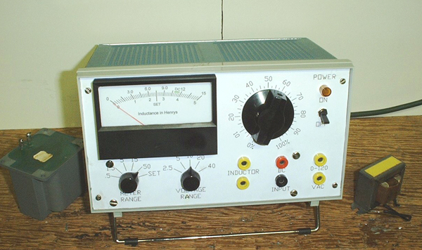
The only thing new is the meter face. Obtain or locate in your junk box a 0 to 1 mA meter movement. Carefully disassemble the meter and remove the metal plate with the scale on it. I strongly recommend you temporarily reassemble the meter to keep dust out of it and prevent accidental damage. Now place the meter face in your scanner with a piece of dark colored paper behind it. This will cause the mounting holes and the edges of the meter face to be readily obvious. Set the scan area to be just a little larger than the face. Scan the image into a program like Adobe Photo deluxe. It is likely you will be able to use the scale but you will have to change the numbers. Use the eraser to remove the old numbers and replace them with what you need. Erase the old designation and replace it with "Inductance in Henrys". Mark the "SET" point at the center of the scale. Zoom in on the scale markings and if they look ragged use the draw lines function to draw new ones right over the top of the old ones. If you mess up a particular line you can use the undo function to remove it and try again. Print out the edited image on tracing paper and lay it over the existing face to see if the scaling (size) between your scanner and printer is correct. If it is the printed image should fit exactly over the meter face. If not you can make small (1/100 inch) changes to the size and try again. When you have the size exactly correct print out the image on Epson Photo Quality Paper and cut away most of the excess paper. Lay the meter face on a light box and lay the printed face over it. I always glue the new face to the back of the metal plate. Practice aligning the printed image with the plate and when you feel confident coat the metal face plate uniformly with rubber cement and lay the paper over it. You will have a few seconds of grace period in which you can move the paper around slightly. When the paper is aligned press it down and place it between two pieces of smooth clean material. I use two scraps of Formica covered shelving. I also use them as background for taking pictures. Weight it down with a couple of transformers and let it dry overnight. Use an Exacto knife to cut off the excess paper and cut out the mounting holes. Carefully reinstall the meter face in the meter and reassemble the meter. The meter face is shown as an example. Your meter will most likely be different and you will have to make your own.
The resistors on the meter range switch should be 1% or better. If you have them or can get them good fore you. I used my DMM to select the exact values out of a plastic drawer of 5% resistors. The newer 1/4 watt carbon film resistors are quite good a majority of them fall within 2% of coded value. Out of a stock of fifty you should find one which falls exactly on the value. These resistors hold the value well after soldering so don't be afraid to solder them to the switch terminals. 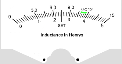
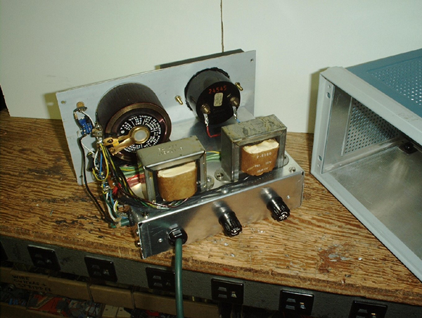
This instrument has a lot of AC running around in it. The circuit board is inside the chassis and the terminal strips, visible in the photograph, are mounted on the outside. The wires which run to the fuses and the voltage range switch under the chassis are shielded.
Calibration
The calibration Resistor.
In the paragraph below you will be instructed to connect a resistor across the INDUCTOR terminals and set the meter to a specific reading. The value of this resistor depends on the power line frequency in your area. For 60 cycle line frequency set the meter to 40 henrys and use a 15.08 k ohm resistor. For 50 cycles set the meter to 38 henrys and use an 11.94 k ohm resistor. You must use your DMM to select this resistor from a number of 15 k ohm or 12 k ohm resistors.Connect a short jumper wire between the two DC INPUT jacks. Connect an AC voltmeter of known accuracy to the INDUCTOR terminals. Set the VOLTAGE RANGE switch to 2.5 and the meter range to .5. Set the variable transformer knob to 0% and turn on the power. Slowly turn the variable transformer clockwise until the external voltmeter indicates .5 volts. Adjust the meter cal trimmer closest to the center of the board until the meter reads 5 on the 0 to 5 scale. This is full scale . Turn the variable transformer knob back to zero and disconnect the voltmeter.
Connect either an 11.94 k ohm or 15.08 k ohm resistor across the INDUCTOR terminals. Set the METER RANGE switch to 50 and the VOLTAGE RANGE switch to 40. Turn up the voltage until the meter indicates either 38 or 40 henrys. See the paragraph above. Change the meter range to the SET position and adjust the gain set trimmer closest to one end of the circuit board until the meter indicates exactly on the SET mark. This last adjustment is what determines the overall accuracy of the instrument so do it carefully.
Operation
This instrument contains integrated semiconductor technology (ICs) and it tests inductors. I admit that's not a good mix. Remember the ignition spark in your car engine is produced by an inductor. ALWAYS BEGIN WITH THE AC VOLTAGE CONTROL ON THE TESTER AND THE VOLTAGE CONTROL ON THE DC POWER SUPPLY SET TO ZERO! Always end a test the same way, I'll remind you of this again.
- Connect a DC power supply to the DC INPUT jacks on the tester. The
supply MUST be one which is capable of being turned all the way down
to zero. If you don't have one, get one!- Turn the power supply on and turn its voltage to zero.
- Turn the AC Voltage control knob (the variable transformer) to 0%.
- Set the voltage range switch to 2.5 volts.
- Connect the filter choke to be tested to the INDUCTOR terminals.
- Set the meter range switch to the 50 henry range.
- Turn on the power to the tester.
- Place the METER RANGE switch in the SET position.
- Slowly turn up the AC voltage control until the meter pointer is on the
SET mark or the knob stops at 100% which ever comes first.- If the knob is at 100% and the meter is still below the SET mark advance
the VOLTAGE RANGE switch one notch at a time until the meter goes
above the SET mark.- Reduce the AC Voltage (variable transformer)
knob until the meter reads on the SET mark.If the choke is NOT marked with specifications skip to step 20.
- Start turning the METER RANGE switch counter-clockwise until the
meter reads more than 1/3 scale.- Read the inductance value from the meter.
- If the choke is marked with specifications the inductance reading
will be high typically about 50%.- If the choke is marked with specifications turn up the voltage of the DC
power supply until its current meter indicates the specified DC current.- Now that you have a substantial DC running through the choke DO NOT
DISCONNECT ANY TEST LEADS! Just don't do it OK?- Place the METER RANGE switch in the SET position. The meter may
or may not indicate on the DC mark but it will read above the set mark.- Turn down the AC Voltage control to bring the meter back to the SET mark.
- Turn the METER RANGE switch counter-clockwise until you can read
the inductance. It should now be close to that specified.- BEFORE TURNING OFF THE POWER ON ANYTHING OR
DISCONNECTING ANY LEADS SET THE AC VOLTAGE
CONTROL ON THE TESTER AND THE VOLTAGE CONTROL
ON THE DC POWER SUPPLY TO ZERO!End of procedure for marked filter chokes. Do not start here for unmarked
chokes; go back to step 1 and come here when instructed to do so.
- If the choke is not marked with specifications slowly bring up the DC
power supply until the meter is in the green region labeled DC. As you
increase the power supply voltage the meter will move to the right and
when you stop turning the knob the meter will return to the true reading.
Move the knob up a little at a time until it gives a steady reading in the green.
After you have performed several tests you will get the feel of this control.- The current meter on the DC power supply is now indicating the DC
operating current for the filter choke.- Reduce the AC Voltage knob until the meter reads at the SET mark.
- Start turning the METER RANGE switch counter-clockwise until the
meter reads more than 1/3 scale.- Read the inductance value from the meter. This is the value you should
substitute into any power supply design equations you are using.- BEFORE TURNING OFF THE POWER ON ANYTHING OR
DISCONNECTING ANY LEADS SET THE AC VOLTAGE
CONTROL ON THE TESTER AND THE VOLTAGE CONTROL
ON THE DC POWER SUPPLY TO ZERO!The End
Thank you for visiting my page at Angelfire.
Please come back and visit again!This site begun March 14, 2001
This page last updated May 21, 2006.