A Dedicated Headphone Amplifier.
Construction details.
I really don't have any interest in writing a complete instruction book in the style of the gone forever and sorely missed Heathkit construction manuals. However I will try to give you enough guidance so you won't go astray in such areas as chassis layout and preventing ground loops.Counting lugs
To count the lugs on a terminal strip hold the strip (or imagine holding the strip) with the lugs pointing up and the side of the strip with the lugs on it facing you. The mounting feet will be sticking out towards you. Count all lugs including grounds from left to right. That's all there is to it.Drilling templates.
Drilling templates are provided below but I don't know of any way to scale them correctly. The scale will depend on your screen resolution and that of your printer. I will provide them in a consistent scaling and it will be up to you to load the images into a graphics program and scale them correctly for your printer. The depth of the chassis is 8 inches front to back. The 12 inch width of the chassis is too large to print on most home printers. I will break the templates into two sections that are smaller than 10 inches, the limit of most printers.If it is possible to scale drawings over the net I wish someone would tell me because I don't know how.
To use the drawings below right click on each one. Then select "Save Picture As..." from the popup menu. The drawings are in GIF format. Save them to a folder where you can find them. Then load one that has the file name "Headphone_Tube-Drill-Left-Top.gif" or "Headphone_Tube-Drill-Right-Top.gif" into your favorite graphics editor. Scale it so its height is exactly 8 inches. Print it out to be sure that the picture height is exactly 8 inches on paper. If not make small adjustments until it is. Scale all six drawings by the same factor and print them out.

Left Rear
Left Top
Left Front
Right Rear
Right Top
Right Front
Drilling the holes in the chassis.
The chassis as supplied by Antique Electronic Supply will have a thin blue plastic film over it. I recommend you leave this film in place until it is time to mount parts on the chassis. It will prevent small scratches and give you a better looking final product.After you get the drawings scaled and printed out cut off the excess paper and attach the drawings to the chassis with double sided scotch tape. Anywhere you see a cross inside of a circle that is a place where you need to drill a hole. Mark the locations with a center punch.
I think it is best to leave the paper templates in place until most of the drilling is done. If you have a very small drill insert a 5/64 bit in it and enlarge the marks left by the center punch. If your drill is large and heavy you may find it better to hold the bit in your fingers. You don't have to drill a hole just cut away a small amount of metal to make the mark large enough so a larger bit won't walk when you drill with it.
Drill the tube socket mounting holes with a 7/64 inch bit and all others with a 9/64 bit. You will enlarge some of the other holes later. The holes for the tube sockets need to be 3/4 inch. You should try to get a chassis punch for making this hole.
A chassis punch consists of two round pieces of steel with a bolt through them. One piece has a curved surface and sharp edges and fits into a hole in the other piece. You place each piece on one side of the chassis with the bolt passing through a hole in the chassis. As the bolt is tightened the sharp piece cuts through the chassis and makes a nice neat hole.A hole saw is less expensive but is not recommended unless you have a drill press. When using a fly cutter or hole saw the chassis must be clamped securely. These devices have a guide drill bit but in the last stages of cutting there is only a small section of the circle still holding and the guiding effect is lost because the piece of aluminum in the center is no longer held firmly in place. 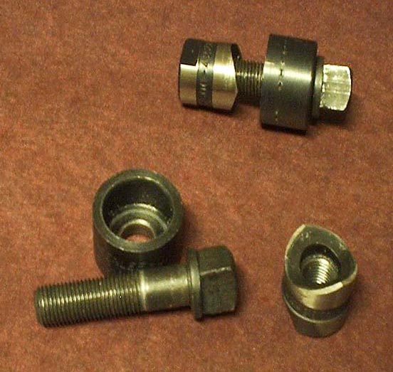
In my case the fuse holder and power switch (chassis left front) required 1/2 inch holes. I did not use the ones I specified so examine your fuse holder and switch to see what size holes to drill. The pots need 5/16 holes. The source selector switch will most likely mount in a 3/8 hole although it may fit in a 5/16 hole.
The specified phono jacks fit in a single 1/4 inch hole. If you elected to use another kind drill the hole or holes appropriate to the jacks you actually have. The magnetic input jacks (J101 and J201) need to be insulated from the chassis. Drill these holes out to 3/8 inch. You can used shoulder washers which have a ridge that forces the jack to be centered in a larger hole. You may want to buy another type of jack and use plastic tape to insulate it from the chassis.
The hole on the right side of the right rear drilling template is for a grounding screw. Almost all turntables have a ground wire and this screw is for connecting this wire.
The two large holes indicated by two concentric circles that are associated with each transformer are for rubber grommets. These will prevent the sharp metal edge of the chassis from cutting through the insulation of the transformer wires. This can happen over a period of years. After drilling the 1/2 inch holes use a small round file to remove the burr (small sharp pieces of metal) that remains from the drilling process.
For smaller holes use a 3/8 inch bit. Hand hold it and turn it in the hole to cut off the burr. If you install the bit in a drill do not run it very long. You don't want to enlarge the hole, just remove the burr.
Lay the bottom plate on the bottom of the chassis and mark the holes to hold it in place. drill the holes with a 3/32 inch bit. You will use number 6 x 1/4 sheet metal screws to hold the bottom plate in place.
After all holes are drilled remove the paper templates and the blue plastic film.
Mounting parts.
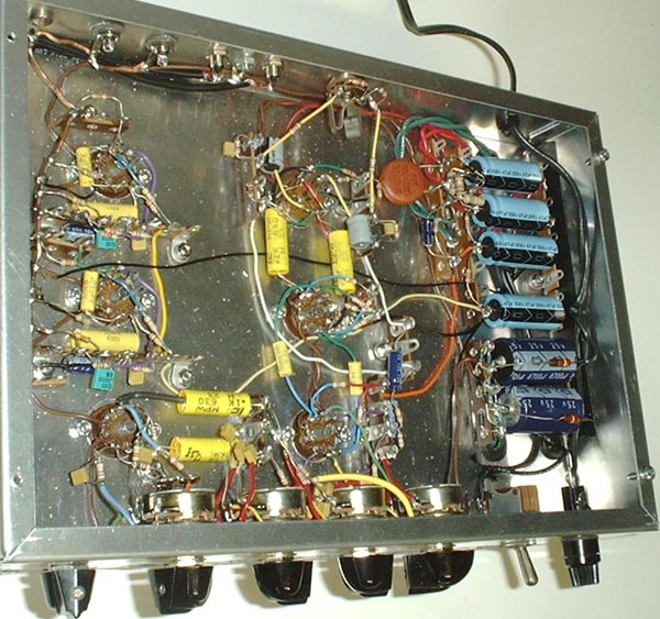
Above is a layout diagram of the chassis. It is viewed from the bottom inside.Place an old towel on your workbench and set the chassis on it. Orient it so the front is toward you and it is upside down.
Mount an unshielded tube socket at V4 as follows.
Push two 4-40 x 1/4 screws through the two mounting holes from the outside of the chassis (bottom as you are holding it) and hold them in place with two fingers.Mount shielded tube sockets at V3, V2, V1, V201, and V101 as follows.Position the unshielded tube socket with the wide space between pins to the right and place it over the screws from the inside of the chassis so the solder terminals are inside.
Place a number 4 lock washer over each screw.
Start a 4-40 nut on each screw. Tighten the screws and nuts.
Insert two 4-40 x 1/4 screws through the mounting holes in a tube socket so the screws are pointing in the same direction as the terminal lugs.Mount all terminal strips except TS13 and TS14 as follows.Insert socket and screws in the chassis hole from the outside and with the wide space toward the right end of the chassis.
From the inside of the chassis place a number 4 lock washer over each screw.
Start a 4-40 nut on each screw and tighten both screws.
Push a 6-32 x 3/8 screw through the hole from the outside of the chassis.TS13 and TS14 share mounting screws with the main power transformer. DO NOT MOUNT THE TRANSFORMER AT THIS TIME.On the inside place a lock washer over the screw.
Place the mounting foot of the terminal strip over the screw.
Place another lock washer over the screw.
Start a nut on the screw.
If the terminal strip has two mounting feet mount the other foot in the same way.
Orient the terminal strip as shown and tighten the screw or screws.
Mount the rear feet of TS 13 and TS14 using 6-32 x 1/2 screws as described above. Leave the screws loose enough so you can mount the front end of each strip.
Mount the front foot of each terminal strip using a 6-32 x 3/8 screw as described above. Tighten the hardware.
At the rear of each strip tighten the hardware just enough so it won't come loose as you work on the chassis. The power transformer will be mounted near the end of construction.
Single point ground.
To keep hum at a minimum all ground connections in each stage must be connected to the same point. In the phono preamp this is extremely important. You need a length of number 14 bare copper wire. Buy a foot or so of insulated #14 wire at a home improvement store and remove the insulation.Place a number 6 solder lug over a 6-32 x 5/8 screw so the bend is toward the head end. Insert this screw through the hole in the rear of the chassis at the left end from the inside. The solder lug should be on the inside sticking out from the chassis.
Place a lock washer over the screw on the outside and start a nut. Tighten it only finger tight.
Phono Jacks.
This is the section you are supposed to read before ordering the phono jacks. If you order the ones I specified they will mount in a single 1/4 inch hole. The ones for the magnetic input MUST be insulated from the chassis to avoid forming a ground loop.The way to insulate these jacks is to use insulating shoulder washers. These washers have a step that makes them thicker near the center hole than at the edge. The center hole is 1/4 inch in diameter and the "shoulder" is 3/8 inch in diameter. If you are using them drill out the two holes for J101 and J201 to 3/8 inch.
Place a shoulder washer on each side of the chassis, inside and out. If the shoulder portion is so thick the outer part of the washer does not touch the chassis, turn one of them over.
Insert the jack from the outside through both washers, place the supplied grounding lug over it and start the supplied nut. Position the center lug and grounding lug toward the top of the chassis as shown in the layout and tighten the nut. Hold the jack with a pair of conventional pliers (not needle nose) on the outside and turn the nut with a nut driver.
The jack must not turn after the nut is tight. If it does, uninstall it and file off some of the thickness of the shoulder washer.
Alternatives.
Antique Electronic Supply has two other kinds of jacks you may wish to use. One type has two jacks mounted on a rectangular piece of phonolic material. These mount with 4 screws and the jacks are closer together than the holes indicated in the drilling template. Plastic insulating tape may be used to keep the shell of the jacks from contacting the chassis. Use a double layer to be on the safe side. Be sure to drill out the holes to a large enough size so the shell of the plugs will not short to the chassis when plugged in.The other choice is a phono jack mounted on a circular piece of phonolic. Each one mounts with two screws. They could be insulated from the chassis with flat insulating washers. This is your project so you pays your money and you takes your choice.
The copper wire.
The #14 wire is not easy to work with. It mainly requires patients. Attempting to use brute force will only result in broken terminals and indigestion. Loosening the nuts on the phono jacks may make it easier to thread the wire through them. 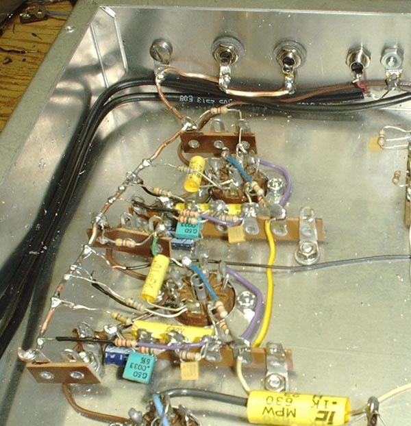
The wire runs through the grounding lugs of jacks J101 and J201, the chassis ground at the grounding screw at the left rear of the chassis, then through lug 3 of TS1, lug 3 of TS3, and ending at lug 2 of TS4A. Do not attempt to make what the Heathkit manuals used to call "... a mechanically secure connection" at the ends of the wire. Just bend a loose hook around the lug as indicated at TS4A. Solder all lugs that the wire passes through. The pictorial diagram and the photo shows a resistor going to the lug at TS1 and TS2. This resistor lead may be wrapped around the wire and soldered as are the other component leads.
Remember to tighten the nuts on the phono jacks and the ground screw.
When soldering to this heavy wire be sure to use enough heat. If the solder beads up on the copper it isn't hot enough. The molten solder must wet the wire not bead up.
DC Heater Wiring.
The following convention has been followed in the pictorial diagram. Cathode wires are Magenta (some would call it purple). Grid wires are green. Plate wires are blue. B+ wires are red. Signal wires away from grids and plates are yellow. Feedback wires are Cyan (light blue). Ground, black.Actual wires in the chassis go this way. Cathode, purple; grid, green; plate, blue; B+, red, orange, or yellow; signal away from grid or plate, yellow; feedback, white; heater, brown; ground, black.
If you have all 10 colors of wire then use color coding. It will make it much easier to trouble shoot the amplifier when something fails some day. Use brown wire for heaters.
Connect a length of brown wire from TS17-2 (that means lug 2 of TS17) to pin 5 of V201. At the TS17 end strip an additional 1/4 inch of insulation making a total 1/2 inch of bare wire. Thread the end through lug 2 (NS) to lug 3 (S1)
The letters (NS) will be familiar to Heathkit builders but for you who were born too late to enjoy that experience, (NS) means No Solder. (S1) means solder, there is one wire in the lug. (S2) means solder two wires, (S3) means solder 3 wires etc.Route this wire straight back along the chassis to the rear, along the corner to the left and out to pin 5 of V201 (S1)Run a length of brown wire from Pin 4 of V201 (S1) to pin 5 of V101 (S1). Route this wire around the terminal strip.
Run a length of brown wire from Pin 4 of V101 (S1) to pin 5 of V1 (S1). Route this wire around the terminal strip.
Run a length of brown wire from pin 4 of V1 (S1) to TS17-4 (NS). Route this wire along the front corner of the chassis.
AC Heater Wiring.
To wire the AC heater circuit you need to make twisted wires. To do this.Cut two equal lengths of brown wire.At one end of a twisted pair of wires connect one wire to TS12-2 (NS) and the other to TS12-3 (NS)At one end clamp both wires in a vise.
At the other end clamp both wire ends in a small drill.
Operate the drill at a slow speed while holding some tension on the wires. Make a little less than one and a half full twists per inch.
Route this wire along the back corner of the chassis and bring it out to V4. At V4 connect one wire to pin 4 (NS) and the other to pin 5 (NS).
The next length of twisted wire goes from V4 to V3. At one end of a twisted pair connect one wire to pin 5 of V4 (S2) and the other to pin 4 of V4 (S2).
At the other end connect one wire to pin 9 of V3 (NS). Remove a little more insulation from the other wire end and connect through pin 5 of V3 (S2) to pin 4 of V3 (NS). Note: When a wire passes through one lug and goes on to another that counts as two wires.
At one end of a twisted pair connect one wire to pin 9 of V3 (S2) and the other to pin 4 (S2).
At the other end connect one wire to pin 9 of V2 (S1). Remove a little extra insulation from the other wire and connect it through lug 5 of V2 (S2) and to pin 4 of V2 (S1).
This completes the heater wiring which was not shown on the pictorial diagram.
Filter Capacitor Grounding.
Connect a length of black wire from TS14-2 (NS) to TS14-4 (NS).Connect a length of black wire from TS14-6 (NS) to TS5-2 (NS).
Connect a length of black wire from TS16-2 (NS) to the magnetic grounding wire (S1). Connect this wire about even with TS2.
Resistors and Capacitors.
Working with pictorial and schematic diagrams install the resistors and capacitors. DO NOT install any of the capacitors in the 300 series just yet. The transformers need to be installed first. Use sleeving over the leads of resistors and capacitors where it looks like there is a chance of them contacting something else. The insulation stripped from hookup wire will fit over the leads of 1/4 watt resistors and the .0022 microfarad capacitors. Use the correct color as illustrated in the chassis photo. The .1 microfarad capacitors will need somewhat larger sleeving.Control Wiring.
Temporarily mount the volume control, tone control and balance control pots on the outside of the chassis. Install all the components and wires that go to, from or between the pots. Make sure every component or wire goes to each lug of each pot and solder them.Unmount the pots from the outside and mount them on the inside of the chassis where they belong. Tighten up the nuts.
Connect the free ends of resistors, capacitors, and wires to the correct terminal strip lugs and when all are present solder the lugs.
Shielded Cable.
The shield should be connected at one end only. This is to prevent ground loops. At the other end there will be ends of shield wires peeking out of the insulation no matter how hard you try to cut them off. Place a short length of heat shrink sleeving over the wire and shrink it down to prevent any chance of a short.The wires from the auxiliary inputs to the switch may have their shields grounded to the grounding lugs on J102 and J202. When you buy new jacks they will be supplied with grounding lugs.
The right phono jack, J201 is so close to the tube socket there is no sense in using shielded wire. The shielded wire from J101 to TS3-1 should have its shield grounded to the copper wire near TS3.
120 V primary wiring.
If not already done install the 4 rubber grommets in the holes next to each transformer. NOW mount the transformers. Mount the 25.2 volt transformer near the front of the chassis as shown.Remove the 1/2 inch screws at the rear of TS13 and TS14. If you are careful the lock washers under the mounting feet of the terminal strips will stay in place. Position the transformer with the green leads at the rear and pull all leads through their respective grommets. Reinsert the 1/2 inch screws through the rear mounting feet of the transformer, through the chassis holes, the lock washers, and the mounting feet of TS13 and TS14. Reinstall the lock washers and nuts on the screws but don't tighten them yet. Install screws, lock washers, and nuts at the front mounting feet of the transformer. NOW tighten all hardware holding the transformer.
Twist the two green leads from the rear transformer together by hand, don't try the drill trick, cut them to length to reach TS12-2 and TS12-3.
Strip about 1/4 inch of insulation, twist the small strands together, and melt a small amount of solder on the wire to hold the strands together.
Connect the wires to TS12-2 (S3) and TS12-3 (S3).
Similarly treat the red wires and route them toward the rear of the chassis, around the ends of TS12 and TS13 to TS12-5 (S2) or (S3)* and TS12-6 (S2) or (S3)*.
* The 3 kV disk ceramic capacitor is optional. If you used it there will be 3 leads in the lugs to be soldered.
Similarly treat the red and yellow lead and connect it to TS14-2 (NS).
Connect one black lead from the rear transformer and one black lead from the front transformer (strip and coat with solder as above) to TS18-1 (NS).
Connect the other black lead of each transformer to one terminal of the on/off switch, S301, (S2). Both leads to the same terminal.
Connect a length of black hookup wire from the other terminal of S301 (S1) to the terminal on the side, NOT the end, of the fuse holder (S1).
The secondary leads of the 25.2 volt transformer, front, may be red or green. The center tap will be the same color but with a yellow stripe. Cut off the center tap and slip a length of heat shrink sleeving over it and shrink it in place.
Strip and tin the solid colored leads and connect one to TS17-1 (S3) and the other to TS17-5 (S3).
Install C301 through C304 at the indicated locations. Be sure to connect the positive end to TS13 or TS15. Be sure all leads are present before soldering.
C306 and C307 are shown as two separate capacitors in the photo and pictorial diagram. You will be using only one capacitor. This is explained at the top of this page under the heading "The DC Heater Power Supply". The same goes for R309 and R310.
If you feel uncertain or confused it may be best to connect the single capacitor in the position of C306 and R309. Connect a length of hookup wire in place of C307. Don't neglect to install the wire from TS18-2 to TS18-4.
Route the end of the line cord through the hole near the rear transformer but don't install the strain relief yet. If you are using a cord with a polarized plug the wire from the wide prong goes to TS18-1 and the other wire goes to the terminal on the end of the fuse holder. Separate the wires of the cord and cut them to length, strip, and tin them.
Connect the short wire (wide prong of a polarized plug) to TS18-1 (S3) and the long lead to the end terminal on the fuse holder (S1).
Place the strain relief over the line cord on the outside of the chassis. Squeeze it down with a pair of pliers and insert it into the hole. Sometimes it takes a lot of squeezing and a lot of pushing to get the strain relief in place.
Initial Checks.
Before installing the tubes make these checks. It would be best to use an analog ohmmeter but if you don't have one you don't have one. Use your digital meter. What you are looking for is a short circuit that would cause something to smoke.Measure the resistance across all 5 capacitors in the power supply and DC heater supply. The reading will start low and go high as the capacitor charges. This will be more evident on an analog meter.
Be sure to change the meter to DC volts. Be careful, these aren't transistors. 350 volts hurts and if current passes through the wrong part of your body, your heart, you can wake up dead.
Install a 1 amp fuse in the fuse holder and connect your meter across C301. Set the range to something higher than 500 volts. The following is known as the smoke test. Plug in the line cord and turn the power switch on.
The meter should read about 360 or 370 volts. If it reads very much lower or something smokes, turn off the switch and unplug the line cord at once.
The voltage across C302, C303, and C304 should be about the same. It may take several seconds for the voltage across C304 to come up to its steady state value.
The voltage across C306 should be about 36 volts. Turn off the power.
Plug 12AX7 tubes into the sockets at V101, V201, V1, V2, and V3. Plug a 6CG7 into the socket at V4.
Connect your voltmeter to pin 3 of V4. Set the range to 20 V. Turn on the power and watch the voltage as the tubes warm up. It should stabilize at about 13 volts. Check the voltage on pin 8 of V4. It should be very close to that measured at pin 3.
If the above test went well you are ready for the final listening test. If not you have some trouble shooting to do. If you have questions feel free to email me. If I didn't want to get questions by email I wouldn't have a web site up for all the world to see.
Listening Test.
Plug a pair of headphones into J1. Use an old pair in case something goes wrong. Do not put them over your ears but let them rest around your neck. Turn on the power.Set the source switch to auxiliary and turn the volume up about half way. Use a small screwdriver to make connection to the center contact of J102 or J202. Simultaneously make contact with the jack and touch the metal part of the screwdriver with a finger. Do not touch the chassis or any other grounded object. This is not because of a shock hazard but to ensure that you will inject the maximum amount of signal into the amplifier.
You should hear a hum in one channel. Touch the other jack and you should hear it in the other channel.
Change the source switch to Phono and repeat the test for J101 and J201. The hum should be much louder and sound quite distorted.
Connect a turntable to J101 (Left) and J201 (Right) and the ground wire to the ground terminal on the amplifier. Or, connect a tape deck, tuner, or other program source to the auxiliary inputs J201 (Left) and J202 (Right). Set the volume control to about 10 o'clock and the tone and balance controls to 12 o'clock.
If no trouble has turned up you can use your best headphones. Turn on the power and listen. You should hear what ever is playing. It should have a transparent sound. Adjust the tone controls to your personal taste.
Turn off the power, unplug the line cord and install the bottom cover. This should eliminate most of the hum. There may be some small amount of hum in the magnetic input but it is far below normal listening level.
ENJOY!
Schematic diagram and circuit description.
Parts list and where to buy them.
Construction details.
A heart in love with the beauty
of glowing tubes never grows old.
This page last updated July 31, 2004.