For a verbal description click here.
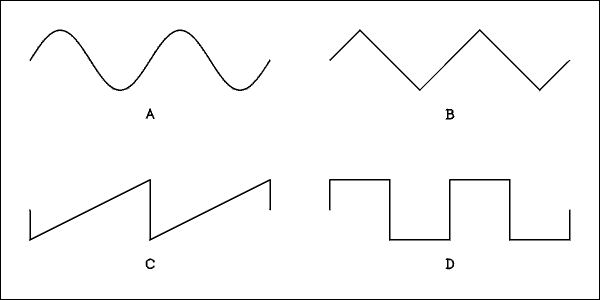
Figure 1, 4 different AC waves.
Electrical Fundamentals.
So, I suppose you think we are walking now? No way! If you can work the problems at the end of the DC Circuits page you pulled yourself up holding onto a chair, took one step, and fell down. If you can't work the problems, what are you doing here? If you didn't fully understand that you don't stand a prayer of understanding what's here.
Basic AC Circuits.All About AC.
Alternating current reverses its direction periodically. The current flows one way for a while and then reverses and flows the other way for a while. The electrons don't move along the wire, they vibrate at the frequency of the alternations.One vibration is called a cycle. The definition of a cycle is; the current or voltage increases from zero to a maximum value, decreases back to zero and continues on to a negative "maximum" and then returns to zero. This definition is stated in general enough terms as to fit any kind of wave shape. The figure below shows 4 different kinds of waves. These drawings are graphs of the voltage or current versus time.
For a verbal description click here.
Figure 1, 4 different AC waves.
Example 2.1
How many cycles of each wave are shown? Follow the wave labeled A with your finger or the point of a pencil while reciting the definition of a cycle. How many times did you recite the definition while tracing the wave. Try to figure this out before you give up. All four waves have the same number of cycles.Solution
Did you get it? The wave labeled A is known as a sine wave because it is exactly the same as the trigonometric sine function. The wave labeled B is a triangular wave, so called for obvious reasons. The one labeled C is a sawtooth wave because it looks like the teeth of a saw. The D wave is called a square wave again for obvious reasons.
How are AC waves created?
A very simple circuit for generating square waves is shown in Figure 2.

For a verbal description click here.
Figure 2, Switching square wave generator.
A note about schematic diagrams is in order. When two wires (lines) have to cross but not connect they just cross. If it is meant for a connection to be made a dot is placed at the crossing. When a line joins another one to form a T a dot is placed there even though this could not be a crossing. The reason for this is to maintain consistency. You can see an example of this in Figure 2.When the switch in Figure 2 is flipped rapidly between the two positions the output voltage changes from positive to negative to positive and so on. A variation of this method is used in the UPS (uninterruptible power supply) that backs up your computer. The switches are transistors rather than a mechanical switch. Another application of this switching circuit is the vibrator in a tube car radio. This is truly a mechanical switch driven by a magnetic coil. This generates square waves which are all right for the circuits in a car radio but are not the best for powering most home electronic devices. Computers and accessories have been designed to work on the square waves from a UPS.
An electric machine called an alternator generates sine waves. The electric utility uses alternators to generate these waves and delivers them to us. They are preferred for reasons I can't explain until you understand frequency.
Frequency and period.
Frequency is the number of cycles each second. The power utility in the United States delivers power at 60 cycles per second. In 1965 a cycle per second was designated as Hertz. There was some resistance to this change because most people thought it was silly. Furthermore, the term cycles per second is descriptive of what it is but the term Hertz leaves one totally uninformed. What year marked the end of vacuum tubes is open to considerable argument, but 1965 is probably as good as any. Since I am reverting to the time before 1965 I have decided to abandon Hertz.Frequency in cycles per second is usually shortened to cycles. It is measured in cycles, kilocycles, megacycles, and gigacycles.
Period.
Frequency is in cycles per second and period is in seconds per cycle. The period is the time required for one cycle. It can be measured in seconds (rarely), milliseconds, microseconds, or nanoseconds. The relationship between frequency and period is.f = 1/T Where f is the frequency in cycles per second and T is the period in seconds.and
T = 1/f
Example 2.2
What is the period of the 60 cycle power line frequency?Solution
Example 2.3
It is possible, and done all the time, to measure the period of a wave using an oscilloscope. Such a measurement gives a period of 4.0 milliseconds. What is the frequency of this wave?Solution
Measuring AC voltage and current.
Measuring AC is a little tricky because meters respond to the average value while The equivalent heating of a resistor works by the RMS value. This can't be proven without using calculus. We are not going to get into that so I will explain it in terms of the early times of electricity.DC meters use a coil of wire and a permanent magnet to make the pointer move across the scale. If AC is applied to the coil the meter is urged to move in one direction when the cycle is positive and in the other direction when the voltage is negative. if the frequency is one cycle or less the pointer will wave back and forth. if the frequency is, say 60 cycles, the pointer will not be able to follow each cycle and will not move at all. If the permanent magnet is replaced by an electro magnet which is excited by the same current as the movable coil the fields from the two coils will result in the force on the pointer always being in the same direction regardless of the polarity of the voltage or current. This does result in a nonlinear scale but that can be worked out. This is how AC meters were made before crystal rectifiers were invented.
OK. Now we have a meter that will measure AC voltage and current but how to calibrate it. These meters will respond to the average value of the AC cycle. The average is exactly what you think it is. If you take the average over a whole cycle you get zero. The trick is to average over just half of the cycle. when you do this you get the average value to be 0.637 of the peak value.
With the AC meter they thought they had it but things didn't come out right. The way voltages were compared was to use two identical light bulbs. When one bulb was powered by a DC generator and the other by an AC generator, and the AC generator was set so its average voltage was the same as the DC generator the light on the AC generator was too bright. Careful measurement showed that to make the two light bulbs have the same brightness the average value of the AC had to be set to 0.9003163 of the DC value.
Equal light from a light bulb means equal power. The mathematicians figured out that power is related to the RMS value of AC. RMS stands for Root Mean Square. Every value of the cycle is squared, the average is taken and the square root of the average is taken. When this is done, by using calculus, the RMS value of an AC cycle is 0.7071 of the peak value. 0.7071 is one over the square root of two.
What you need to remember is that the RMS value is 0.7071 of the peak and the peak is 1.414 times the RMS value. 1.414 is the square root of two and 0.7071 is one over the square root of two. If you have trouble remembering which one to use just remember that the peak value is the highest part of the wave and therefor is the largest value. If you want to calculate the peak value given the RMS value and you wind up with a smaller number you did it wrong. The peak value is always larger than the RMS value.
Why use sine waves?
When an alternator or an electronic circuit is generating a sine wave just one frequency is being generated. That may seem to be a "why of course" statement but it isn't always true. Suppose the switching circuit of Figure 2 is in operation at a frequency of 1 kc. The frequency 1 kc is being generated along with the frequencies 3 kc, 5 kc, 7 kc, 9 kc 11 kc, and so on all the way up to infinity. The voltage of all these frequencies is not the same. If the 1 kc frequency has a voltage of 1 volt, the 3 kc frequency will have a voltage of 1/3 volt, the 5 kc frequency will be 1/5 volt, the 7 kc frequency will be 1/7 volt, you see the trend don't you? by the time you get up to 1001 kc, they always have to be odd, the voltage is 1/1001 which is pretty small. These frequencies which are above the original one are called harmonics. The starting frequency is called the fundamental frequency. Any wave which differs from a sine wave will have harmonics associated with it.Speaking of AC.
AC voltages and currents are given in RMS unless otherwise noted. When we say the electric utility voltage is 120/240 volts these are RMS values. All meters are calibrated to read out the RMS value of a sine wave. If the wave is other than a sine wave some meters will still read the true RMS value and others won't. If you want to measure voltage and current of non sinusoidal waves you need to check the manual for your meter to find out if it is a true RMS meter or not.How does Ohm work with AC?
As long as the circuit contains only resistors the formulas for Ohm's law and power work the same as they did for DC. The only thing you need to be sure of is to be consistent in using RMS or peak to peak. An oscilloscope will most easily measure P-P (peak to peak) voltage. If you start using RMS you have to keep using it through out the calculation. Same for P-P. Power calculations MUST use RMS values.Because the current is directly proportional to voltage, the current and the voltage are said to be in phase. If you plot the waves of voltage and current versus time the two waves will cross zero and reach their peaks at the same time. Although this may seem obvious we are about to examine cases where this is not true.
Capacitors.
The schematic symbol for a capacitor shows exactly what it is, an open circuit. It's the most useful open circuit ever discovered. It acts like a flywheel for voltage. If you start out with zero voltage across a capacitor you have to do some work to put some voltage across it just as you have to work to get a top spinning. (Any wheel that spins acts as a flywheel.) You have to do some work to change the voltage across a capacitor. In electricity doing work usually means delivering current. Although a capacitor is an open circuit, current will flow into or out of it when the voltage is changing. When the voltage stops changing, the current stops. The current flowing into or out of a capacitor is given by

Where I is the current in amps, C is the capacitance in farads, V is the voltage in volts, and t is the time in seconds. In this equation the triangular symbol, which is pronounced "delta" is shorthand for a change in the voltage or time. Instead of writing V2 - V1 and t2 -t1, we write delta V and delta t.The way this equation is stated assumes that the current changes little, or not at all, during the time interval delta t. The interval must be chosen small enough to obtain good accuracy. If the intervals are made smaller and smaller until they are infinitesimal the equation becomes a calculus problem, but we are not going to go there.
Example 2.4
If a 40 microfarad capacitor is discharged from 150 volts to 120 volts in 16 milliseconds, what is the current?Solution
Example 2.5
What size capacitor should be used in a full wave power supply if the peak to peak ripple is to be no more than 10 volts and the load current is 100 mA? Full wave power supply means that the discharge time for the capacitor is approximately 8 milliseconds. (The full wave rectifier gives a ripple frequency of twice the line frequency which would be 120 cycles. The period is 8.333 milliseconds. The capacitor charges for a very short time and discharges for most of the cycle.) The peak to peak ripple is how much the capacitor charges up and then discharges. The load current of 100 mA will discharge the capacitor by 10 volts in 8 milliseconds. Enough hints; work the problem already.Solution
When an alternating voltage is applied to a capacitor an alternating current will flow. There is current flow when ever the voltage is changing. The sine wave of voltage changes continuously except for an instant of time when it reaches the positive and negative peaks. When the voltage is at a peak the current is passing through zero. This means that the current and voltage are 90 degrees out of phase. To decide if the current is leading or lagging would require some rather abstruse reasoning. I will just tell you that the current leads the voltage by 90 degrees and you will have to learn calculus or take my word for it. The phase relationship between voltage and current is shown in Figure 4.
Power in AC Circuits.
In an AC circuit power is not always simply volts times amps. It depends on what is in the circuit. As long as there are nothing but resistors in the circuit it is simply volts times amps as shown in Figure 3.
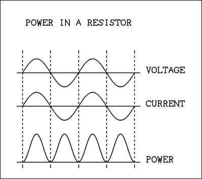
For a verbal description click here.
Figure 3. Waveforms of the current, voltage, and power in a resistive circuit.
The instantaneous power is the product of voltage and current from microsecond to microsecond. In the drawing above when both voltage and current are zero the power is zero. When voltage and current go positive the result is positive power. That means energy is flowing from the generator to the circuit. When both voltage and current are negative the power is positive because a negative number times another negative number gives a positive number. The power is all positive but it goes to zero twice during each cycle of the generator frequency. This accounts for the humming sound made by AC motors. The power to the motor, and hence its torque drop to zero 120 times a second (in the US).Now if you connect a capacitor across the AC power line, or a signal generator, current will flow but the power will be zero. (There may be a small amount of power because capacitors are not absolutely perfect. Most are about 99 percent efficient so the power measured by a watt meter would be very small.)

For a verbal description click here.
Figure 4. Waveforms of the current, voltage, and power in a capacitive circuit.
If you are wondering how the current can begin at the top, it didn't. Things have been going on for a while. the beginning of the graph is where we started watching.First of all since the power is the product of voltage and current, if either is zero at any instant the power will be zero at that instant. For the first 90 degrees the voltage increases from zero to maximum while the current decreases from maximum to zero. Both are positive so the power starts at zero, rises to a positive maximum and falls back to zero at 90 degrees.
For the next 90 degrees the voltage is positive but the current is negative. That produces a negative power. The average of the power curve is zero because it is equally above and below the zero axis. The capacitor takes some energy from the generator and then gives it back. Yes Virginia, it is possible to have voltage, current, and zero power.
Because the current and voltage are 90 degrees out of phase you can't say that what causes current to flow is resistance. It is called reactance. The reactance of a capacitor changes as the frequency changes. It starts out at infinity for DC (zero frequency) and decreases as the frequency gets higher. The equation for capacitive reactance is,

Where Xc is the reactance in ohms, that's right I said ohms, f is the frequency in cycles per second, and C is the capacitance in farads. If you use frequency in Megacycles and capacitance in microfarads the reactance will also come out in ohms. We will see later how the calculation of reactance is important.Example 2.6
What is the reactance of a 0.01 microfarad capacitor at 20 cycles?Solution
Example 2.7
If a 40 microfarad capacitor is connected across the 120 volt 60 cycle power line, how much current will flow? How much power will be dissipated?Solution
Inductance.
Inductance is what a coil of wire has. In many ways it is the opposite of capacitance. Capacitance is a flywheel for voltage, inductance is a flywheel for current. A capacitor is an open circuit for DC, an inductor is a short circuit for DC. The AC current leads the voltage in a capacitor, the current lags the voltage in an inductor. In fact there is a useful pneumonic (memory aid) that goes like this.ELI the ICE man.
E is used as a symbol for voltage, I for current, L for inductance and C for capacitance. In a capacitor (c) the current (I) leads (comes before) the voltage (E), ICE. In an inductor L the current lags the voltage so the voltage leads the current. If you are following me I am leading you. The voltage (E) leads the current (I) ELI. Eli the ice man has gotten many electrical engineering and physics students through that first course.Power in Inductive circuits.
In a pure inductor the current lags the voltage by 90 degrees. The same situation as a capacitor applies here. The power is zero as shown by the graph below.
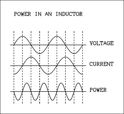
For a verbal description click here.
Figure 5. Waveforms of the current, voltage, and power in an inductive circuit.
Once again the beginning of the graph is not when the power was turned on. The power has been on for a while and we just started watching.First of all since the power is the product of voltage and current, if either is zero at any instant the power will be zero at that instant. For the first 90 degrees the voltage increases from zero to maximum while the current increases from a negative "maximum" to zero. The voltage is positive and the current is negative so the power starts at zero, goes down to a negative "maximum" and comes back to zero at 90 degrees.
For the next quarter cycle the voltage and current are positive. That produces a positive power. The average of the power curve is zero because it is equally above and below the zero axis. The inductor takes some energy from the generator and then gives it back.
Because the current and voltage are 90 degrees out of phase you can't say that what causes current to flow is resistance. It is called reactance. The reactance of an inductor changes as the frequency changes. It starts out at zero for DC (zero frequency) and increases as the frequency gets higher. The equation for inductive reactance is,

Where XL is the inductive reactance in ohms, f is the frequency in cycles per second, and L is the inductance in henrys. You can use frequency in kc and inductance in millihenrys or frequency in Mc and inductance in microhenrys and the reactance will come out in ohms.Example 2.8
What is the reactance of a 300 microhenry inductor at a frequency of 455 kc?Solution
The black sheep inductor.
The inductor has an image problem. For one thing it is somewhat inefficient. Inductors are coils of wire. Wire has resistance. So an inductor is a mixture of inductance and resistance. Furthermore it is big. It has to be made of heavy wire, to minimize the resistance and in millihenry values it usually needs a powdered iron core, and in henry values a heavy laminated iron core. In small values inductors can be printed on a PC board but they can't be fitted into an integrated circuit. For these reasons the poor old inductor is despised, discriminated against, and rejected by the IC crowd. "Would you want your capacitor to marry one?"Those of us who work with tubes aren't concerned with trying to make our circuits so small we need to work on them under a microscope. In fact those big filter chokes in the power supply and those tank coils in the finals of a transmitter are quite comforting. It's quite relaxing to know you can work on it with ordinary tools rather than tweezers and Exacto knives.
Basic RC Circuits.
No, I'm not talking about an RC and a moon pie. In this context RC stands for Resistance - Capacitance. You can accomplish some amazing things with a resistor and a capacitor. One thing you can do is to make a delay circuit. You may want to have circuit B come on one minute after switch A is closed. Oh, yes you could use a 555 timer but even that not so modern device (they came out in the late 70s) uses an RC circuit to do the delaying. (I think it's really funny that there is a senator named Delay. But I digress.) The basic delay circuit is shown in Figure 6.

For a verbal description click here.
Figure 6. RC Charging circuit.
When the switch is set to the lower position the capacitor is discharged. Then at time = zero the switch is flipped to the upper position. Because the capacitor is completely discharged (zero voltage), for an instant, all of the battery voltage is dropped across the resistor. (Remember how we added up voltages around a circuit.) A current of E/R flows into the capacitor and it's voltage will begin changing at a rate determined by the value of the capacitor and the magnitude of the current. As soon as the capacitor voltage begins to change (increase), the current will be decreased by the fact that some of the resistor voltage is being taken away by the capacitor. That reduces the charging current and makes the capacitor charge more slowly. As the capacitor continues to charge the resistor has less and less voltage across it so the current is less and less. The capacitor continues to charge but more and more slowly as time passes. A graph of the capacitor voltage is shown in Figure 7.

For a verbal description click here.
Figure 7. Charging curve of an RC circuit.
The voltage is approaching the line labeled E but it will never get there. If you stand in the middle of the room facing a wall and take a step of half the distance to the wall. Your next step is half of the distance left. Next step is half of the distance left. You will never get to the wall because the rules say you can't take a step of the whole distance. You must always take a step of half of what's left. You can get as close as you want to but you never can get there. That's how the capacitor voltage is approaching the battery voltage. For practical purposes, as you approach the wall, there is a point where you can no longer see the space between your foot and the wall. Similarly, there is a point where you can't tell the difference between the capacitor voltage and the battery voltage.When the capacitor voltage reaches 63.21206 percent of the battery voltage a time of one time constant has passed. Time constant (T) is given by,
T = R C
Where T is the time constant in seconds, R is the resistance in ohms, and C is the capacitance in farads. If the sensor is made to trigger when the voltage reaches 63.21206 percent of the battery voltage then circuit B will come on one time constant after the switch is thrown. If R is 10 meg ohms and C is 6 microfarads the time constant is 60 seconds. Meg ohms times microfarads is the same as ohms times farads.To finish the story, if the capacitor is allowed to charge up to the point of being indistinguishable from the battery voltage and then the switch is flipped to the lower position the capacitor voltage will fall as shown in Figure 8.

For a verbal description click here.
Figure 8. Discharging curve of an RC circuit.
After one time constant the voltage is down to 36.78794 percent of its starting value. At the end of each time constant the voltage is down to 36.78794 percent of whatever it was at the start of THAT time constant.RC Filter Circuits.
RC filters are used so extensively in electronic circuits, if you don't understand what they do you will be mostly in the dark about how most tube (and transistor for that matter) circuits work. The most commonly found application is to separate AC from DC.High Pass RC Filter.
In Figure 9 below the input sine wave is high in the air above the zero axis. It's like having a battery in series with an AC generator. The voltage on the plate of a tube amplifier is like this. There is a basic DC level which moves up and down a little. The capacitor is an open circuit for DC so none of it comes through the RC circuit and the output wave is the AC only; the sine wave is symmetrical about the zero axis. The capacitor has to charge up to the DC value. If the resistor were absent there would not be anything to cause the capacitor to charge and the output wave would look the same as the input wave.

For a verbal description click here.
Figure 9. A high pass filter with input and output waves.
This circuit is called a high pass filter because it passes high frequencies. Remember the equation for the reactance of a capacitor? Xc gets larger as the frequency gets lower. When the reactance is much less than the resistor the AC signal is passed on to the output with virtually no change in amplitude. At the frequency where the reactance is equal to the resistor the amplitude of the output is 0.707 of the input signal (-3dB). This does not happen suddenly; the output changes gradually. Below this -3dB frequency the output falls off rapidly as the frequency is reduced. DC is as low as the frequency can get so it really gets cut out.It is somewhat unfortunate that the frequency where Xc = R is called the "cut off" frequency. This can leave the neophyte with the impression that frequencies below the so called cut off frequency just disappear and the rest are uneffected. Nothing could be further from the truth.
As the frequency approaches cut off from above the output begins to be slightly effected at a frequency ten times the cut off frequency. The output gradually decreases until it is 0.707 of the input at the cutoff frequency. Below that point the attenuation increases, the output voltage decreases until it is 1/10 of the input at a frequency of 1/10 of the input. At a frequency of 1/100 of the cut off the output is 1/100 of the input and so on.
The attenuation ratio of a high pass filter at any frequency may be calculated using the formula,
Where Ar is the output voltage divided by the input voltage, called the attenuation ratio. Xc must be recalculated for each frequency. 
Example 2.9
A 0.01 microfarad capacitor and a 15900 ohm resistor are connected to form a high pass filter. What is the attenuation ratio (Ar) at frequencies of; (a) 10 cycles, (b) 100 cycles, (c) 1000 cycles, and (d) 10 kc?Solution
Low Pass RC Filter.
If you interchange the resistor and capacitor the circuit works in reverse. The same mix of AC and DC comes out all DC. Now the capacitor is in parallel. the DC is not effected by it so it comes through to the output. The capacitor presents a very low reactance to the AC signal and shorts most of it out. The result is shown below.

For a verbal description click here.
Figure 10. A low pass filter with input and output waves.
This circuit is called a low pass filter because it passes low frequencies. Remember the equation for the reactance of a capacitor? Xc gets smaller as the frequency gets higher. When the reactance is much greater than the resistor the AC signal is passed on to the output with virtually no change in amplitude. At the frequency where the reactance is equal to the resistor the amplitude of the output is 0.707 of the input signal (-3dB). This does not happen suddenly; the output changes gradually. Above this -3dB frequency the output falls off rapidly as the frequency is increased. DC is as low as the frequency can get so it remains uneffected by the circuit.It is somewhat unfortunate that the frequency where Xc = R is called the "cut off" frequency. This can leave the neophyte with the impression that frequencies above the so called cut off frequency just disappear and the rest are uneffected. Nothing could be further from the truth.
As the frequency approaches cut off from below the output begins to be slightly effected at a frequency 1/10 of the cut off frequency. The output gradually decreases until it is 0.707 of the input at the cutoff frequency. above that point the attenuation increases, the output voltage decreases until it is 1/10 of the input at a frequency of 10 times the input. At a frequency of 100 times the cut off the output is 1/100 of the input and so on.
The attenuation ratio of a low pass filter at any frequency may be calculated using the formula,
Where Ar is the output voltage divided by the input voltage, called the attenuation ratio. Xc must be recalculated for each frequency. 
Example 2.10
A 0.1 microfarad capacitor and a 15900 ohm resistor are connected as a low pass filter. Calculate the attenuation ratio (Ar) at frequencies of; (a) 10 cycles, (b) 100 cycles, (c) 1000 cycles, and (d) 10 kc.Solution
High pass filters are used to couple signal from the plate of one tube to the grid of the next without letting the DC get through. They can also be used to attenuate unwanted low frequencies such as turntable rumble. Don't know what turntable rumble is? Ask dad or granddad.
Low pass filters are used in power supplies. The output from a rectifier is a mix of AC and DC although not exactly as pictured in Figure 10. The filter can reduce the AC component to a very low value. They can also be used to attenuate unwanted high frequencies such as surface noise from records. Go back and ask dad or granddad again.
Resonance.
There is a problem in teaching resonance. The series resonant circuit is easy to understand and for university students is easy to analyze mathematically. The problem is that most resonant circuits found in the real world are of the parallel type. parallel resonant circuits are a bit more difficult to understand and a lot Moore difficult mathematically. This is why physics and introductory electronics and electrical engineering courses usually cover series resonance and ignore parallel resonance. We will begin with series resonance but we will not ignore the real world of parallel resonant circuits.Series Resonant circuit.
Here is the circuit. For those unacquainted with the symbol the circle with a little sine wave in it is an AC generator. It is a perfect voltage source which means it has zero internal resistance.

For a verbal description click here.
Figure 11. Series Resonant Circuit.
The resonant frequency is determined by the values of L and C. Let us assume that the generator frequency is at the resonant frequency. Because this is a series circuit the current in any component in the circuit is the same as that in any other component in the circuit. For AC the additional statement may be made that the current has the same phase anywhere in the circuit.The voltage across the resistor is in phase with the current. The voltage across the inductor leads the current by 90 degrees. The voltage across the capacitor lags the current by 90 degrees. The total difference in voltage phase between the inductor and capacitor is 180 degrees. If two sine waves that are 180 degrees out of phase and equal voltage are added together point by point the result is zero.
If you connect a voltmeter across the capacitor alone you will read a voltage higher than the generator voltage (more about this later). Similarly, if you connect a voltmeter across the inductor alone you will read the same voltage as the capacitor. But if you connect the voltmeter across both you will read zero. If you connect the voltmeter across the resistor you will read the generator voltage. This cancellation effect is what makes resonance, resonance.
Say the generator is 1 volt and the frequency is 1 kc, the resistor is 1 ohm, the inductor is 15.915 mH (millihenrys), and the capacitor is 1.5915 microfarads. So let's calculate the reactances of the capacitor and inductor. We will work the capacitance in megacycles and microfarads.
Xc = 1/(2 Pi f C) = 1/(2 x Pi x .001 Mc x 1.5915 mu f) = 100 ohms. Any bets on whether I worked out that value in advance? Now lets work out the inductive reactance. We'll use kc and millihenrys.XL = 2 Pi f L = 2 x Pi x 1 kc x 15.915 mH = 100 ohms. Surprised? The definition of resonance is the frequency where Xc = XL. Because the reactances are equal the voltages are going to be equal and cancel. The voltage across the resistor is equal to the generator voltage which is 1 volt. The resistor is 1 ohm so the current in the circuit is 1 volt / 1 ohm = 1 amp. Hugh, that was a hard one. Now the voltage across the capacitor is 1 amp x 100 ohms = 100 volts. That's right! The voltage across the capacitor, or the inductor, is 100 volts.We're not getting something for nothing. There is not more power, just more voltage. As the frequency moves off resonance the current in the circuit and voltage across the capacitor or inductor falls off rapidly. The impedance of this circuit is plotted in Figure 12.

For a verbal description click here.
Figure 12. Impedance Plot of a Series Resonant Circuit.
The impedance comes down to a minimum of 1 ohm at the resonant frequency of 1000 cps. This makes the current rise to a maximum and fall off quickly away from resonance.The calculation of impedance gets much more complex than what we did above. The current in the circuit is I = V / Z where,
When XC = XL the above equation reduces to the square root of R squared which is Z = R. That's what makes calculations so easy at resonance. If you are ambitious and have a scientific calculator try calculating the impedance, circuit current, I = E / Z, and voltage across the capacitor at frequencies of 1010 cycles, and 1050 cycles. Don't forget to use the new values of XC and XL not 100 ohms. 
Quality Factor.
When electronics types speak about tuned circuits they often talk about Q. Q is the symbol for the quality factor. The Q is a measure of the band width of the resonance curve and also the efficiency of the circuit. The Q of a series resonant circuit may be expressed in two ways.Delta f is the frequency span between the two points where the response of the circuit is down by 3 dB from the peak, as shown in Figure 12. We calculated the current at the peak as 1 amp so 3 dB down would be 0.707 amp. For this to happen the impedance would have to be up to 1.414 ohms from 1 ohm at the peak. In Figure 12 the frequencies at the -3 dB points are 995 and 1005 cps. It is left as an exercise to calculate the Q of the above circuit by the two equations. 
Example 2.11
Calculate the Q of the above circuit by (a) XL over R, and (b) f over delta f.Solution
Example 2.12
An AM broadcast receiver should have an IF bandwidth of 15 kc. The center frequency is 455 kc. Calculate (a) the required Q, and (b) the series resistance if the inductor is 500 microhenrys.Solution
Parallel resonance.
Parallel resonant circuits are used in the plate and grid circuits of tubes to make tuned amplifiers. The type of tube used is usually a pentode which has a high plate resistance. This makes the tube a voltage generator in series with a large resistor. The grid circuit is an open circuit, except in class C amplifiers, so the impedance is high. That's important because placing a low impedance across a parallel resonant circuit will make its bandwidth very broad. Figure 13 shows a parallel resonant circuit.
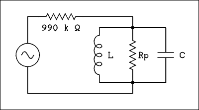
For a verbal description click here.
Figure 13. A Parallel Resonant Circuit.
Lets use the same values of L and C as in the series resonant circuit above. L = 15.915 mH, and C = 1.5915 microfarads. The resistor Rp will be 10 k ohms. At resonance XL = Xc. The voltages across Rp, L, and C, are equal and in phase. The current through the capacitor leads the voltage by 90 degrees. The current through the inductor lags the voltage by 90 degrees. The total difference in phase between capacitor current and inductor current is 180 degrees which means they cancel. The current circulates around the loop of the inductor and capacitor but does not appear in the 990 k ohm resistor. The only current flowing in the 990 k ohm resistor is the current flowing through the resistor labeled Rp which is 10 k ohms.If the voltage generator is 100 volts the current is I = 100 volts / (990 k ohms + 10 k ohms) = 100 volts / 1 meg ohms = 100 microamps. The voltage across the tuned circuit is 0.1 mA times 10 k ohms = 1 volt.
As the frequency moves below resonance the reactance of the inductor decreases while the capacitive reactance increases. The cancellation effect goes away and the effective impedance of the circuit decreases,; the voltage across the circuit will decrease. Far from resonance the inductive reactance will be very small and the total circuit impedance and the voltage will also be very low.
As the frequency increases above resonance the capacitive reactance decreases and the inductive reactance increases. The capacitive reactance now dominates lowering the circuit impedance. The impedance and circuit voltage decreases as the frequency goes above the resonant frequency.
So the impedance of a parallel resonant circuit is maximum at resonance and decreases away from resonance. The calculations in parallel resonant circuits are not easy and will be passed over. Electrical engineers use a thing called the j operator to make such calculations. The reader who is curious and ambitious should enroll in an electrical engineering program. The graph of impedance versus frequency for a parallel resonant circuit is shown in Figure 14 below.

For a verbal description click here.
Figure 14. Impedance Plot of a Parallel Resonant Circuit.
The maximum impedance of this circuit is unusually low due to the values of L and C. For something like an IF transformer in an AM radio a maximum impedance of 100 k ohms is not at all unreasonable. The Q of a parallel resonant circuit is given by,Where Rp is the effective resistance in parallel with the inductor and capacitor, XL is the reactance of the inductor at the resonant frequency and F and delta f are as defined in Figure 14. 
As mentioned in the solution to example 2.12 there are rarely real resistors in a resonant circuit. In the diagram of the parallel resonant circuit above neither resistor is real. The 990 k ohm resistor symulates the plate resistance of a tube and the resistor labeled Rp is the effective parallel resistance caused by the series resistance of the wire used to wind the coil. The effective parallel resistance is calculated by,
Rp = Rs Q2. Where Rp is the effective parallel resistance, Rs is the resistance of the coil, and Q is the Q of the coil at the resonant frequency, given by XL / R.Resonant Frequency.
The resonant frequency of either a series or a parallel circuit may be calculated by,
Example 2.13
What value of inductance should be used with a 365 pf capacitor to resonate at a frequency of 530 kc?Solution
The decibel (dB).
What the heck is a decibel? I could have made that rhyme but I want to keep these pages strictly G rated. A decibel (dB) is one tenth of a Bel, as in Alexander Graham. OK, so what's a Bel? Well, it's 10 ----- never mind. Decibels and Bels started life as measures of sound level. Because the telephone turned sound into electrical current it didn't take long before the dB was used to characterize electrical values.In terms of sound a dB is the smallest change in sound level that an average person can detect. Already you see that the dB is a measure of a difference. Furthermore, human hearing was found to be logarithmic instead of linear. A measurement expressed in dB has to be a comparison of one electrical value to another. You just can't convert a voltage into dB. There has to be a voltage that it is being compared to. That can be a specified voltage such as dBV, dB compared to 1 volt, or dBm, dB compared to the voltage that produces 1 milliwatt in a 600 ohm resistor. The latter results from the fact that telephone lines operate at an impedance level of 600 ohms.
To make a long story short dB may be calculated by the formula
The attenuation of a network or the gain of an amplifier are expressed as a ratio of two voltages. The dB is a convenient way of expressing attenuation or gain. They are really the same thing, just output voltage divided by input voltage. Many authors reduce the two to one parameter. Gain as the name implies is an increase and so the gain expressed without dB is a number greater than 1. Attenuation is a reduction and so is a number less than 1. The log of a number greater than 1 is positive and the log of a number less than 1 is a negative number. The log of 1 is 0. An amplifier with a gain of 0 dB has a gain of 1. That may seem like an oxymoron because 1 is no gain at all so how can it be called a gain of 1. The answer is "That's just the way it is". There is an amplifiers circuit that has a voltage gain of 1 but it has a power gain greater than 1. 
The gain of an amplifier expressed in dB is a positive number. Attenuation is a negative number. So if we have a string of amplifiers and attenuators how can we figure out the total gain? We can take the gains and attenuations expressed without dB and multiply them together. But remember that trick with logs? Adding logs is the same as multiplying the numbers. The dB gains and attenuations can be added together to get the overall gain of a device such as an integrated stereo amplifier.
And in case you are wondering why we would put attenuators in an amplifier, think of the answer to this question. Ever heard of a volume control?
Example 2.14
Convert the following gains and attenuation ratios to dB. (a) 0.707, (b) 18.5, (c) 2.0, (d) 10, (e) 31.6, (f) 100, (g) 0.5, (h) 0.1, and (i) 0.01.
This page last updated February 14, 2004.
Home