Here is the layout for the EL34 stereo amplifier. It is a 17 by 10 by 3 inch chassis.
A verbal description of this diagram is very difficult to do and would be quite long. If you think you could benefit from such a description, email me.
Oops.
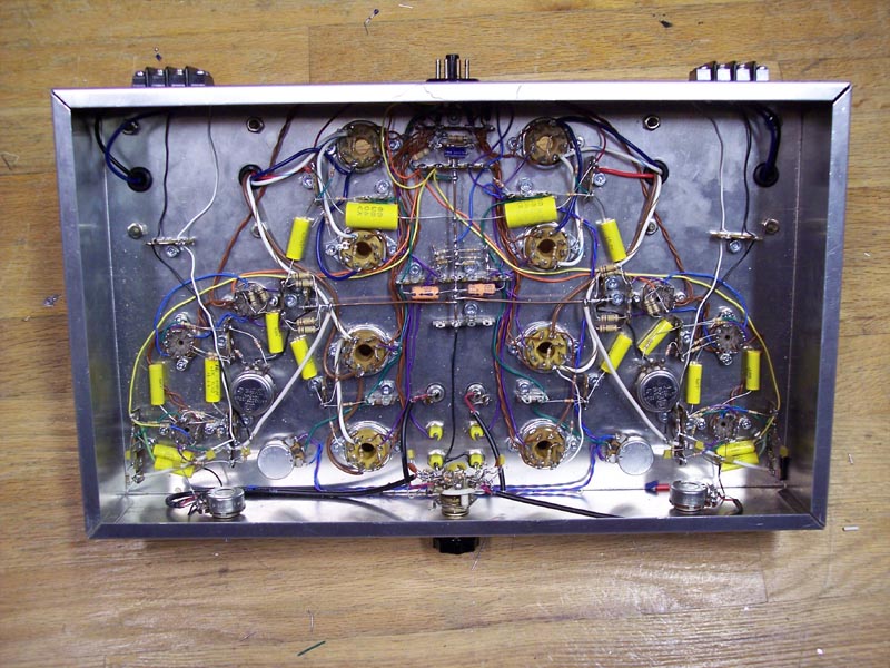
I wired it up with the output transformer leads reversed making positive feedback. The easiest thing for me to do was to reverse the secondary leads. The layout drawing indicates that the brown transformer lead goes to the back tubes while the photo clearly shows the blue leads going to the back tubes. Wire it by the drawing not the photograph.The Layout Drawing.
First of all, let's get oriented. The front of the chassis is to the bottom of the diagram and the back is toward the top. The view is from the bottom. A drilling template is provided below.The color code is as follows.
- Black -- Ground or components that might have two colors.
- Red -- B+1.
- Yellow -- B+2 and B+3.
- Green -- Grid Leads.
- Cyan (Light Blue) -- Feedback.
- Blue -- Plate leads.
- Magenta (Purple) -- Cathode Leads.
There is one exception to this color code. The heater connections from the power plug to the terminal strip are shown in green. This is because the actual wire used is green.
The Purple pots that are shown in rear view are in a cathode circuit which makes them the AC balance pots. The Green pots are in a grid circuit which tells you they are the bias pots. The two pots shown in green and side view, mounted on the front of the chassis, are the input level pots. Note the green capacitor that connects from one of the pot terminals to the grid of the nearby tube. The two capacitors which are underneath the level pots are the B+3 bypass capacitors, 0.1 uf, are connected to B+3 on one end and to ground on the other end.
The 8 octal tubes are obviously the EL34s. The 9 pin mini tubes nearest the lines of 4 EL34s and in the middle of the line are the 6CG7s. The two 9 pin mini tubes a little farther from the lines of EL34s and farthest from the front are the push-pull amplifier composed of the two halves of a 12AX7. The 9 pin mini tubes closest to the front are the first amplifier and phase splitter.
Getting Started.
The diagram does not show every wire. The heaters have been omitted to keep the diagram from becoming too cluttered. The speaker terminals and input jacks, and their wiring, have also been omitted. The output transformer primary wiring has only been shown on the left side. The sleep switch is also missing in action. A detailed description of the heater wiring is given below. The drilling templates for the chassis front and back in combination with the schematic diagram should make it clear how to place and wire these omitted components. I don't know what kind of speaker terminals you are going to use so I can't make drilling patterns for them.Someone sent me an email pointing out that because the input jacks are so far apart an ordinary stereo cable could not be used to connect to them. You could always change it: I have done that myself. No matter where they are placed they are close to something that they shouldn't be close to. In the middle is the power plug with its high current AC heater wires, at the two back corners are the two output transformers with their strong magnetic fields, and between are the power output tubes with their high voltages. I have decided to place the input jacks on top of the chassis near the cathode current jacks. A cable clamp at the rear of the chassis will hold the stereo cable and keep it from getting in contact with the hot tubes. The input jacks are shown in green on the layout view and in black on the drilling template. The jacks should be insulated from the chassis and grounded only through the shields of the cable that connects them to the sleep switch or the input level controls. The shields and level pots should be grounded to the ground wire near the first 12AX7.
If you install the sleep switch run shielded wire from the jacks to the sleep switch and from there to the input level pots. Mount an extra terminal strip near the switch to connect the shield wires together and ground the resistors. Do not ground them to the chassis.
If you don't use the sleep switch, and I think this is more likely, you must run shielded wire from the input jacks to the pots as shown. Although I show a single wire, use shielded wire.
Print the drilling template below and drill all holes.
A verbal description of this diagram is very difficult to do and would be quite long. If you think you could benefit from such a description, email me.
Mount all sockets and terminal strips.
Do not mount the transformers until the end. The chassis will be a lot easier to handle without them.
Back and Front.
Here are drilling templates for the front and back of the chassis.
If you mount the input jacks on top near the front as discussed earlier don't drill the holes for the input jacks in the rear face of the chassis.
The only thing left to your imagination is the speaker connection. There are several alternatives. One is the quick connect blocks in which you push a small lever and a hole opens up into which you push the end of the stripped wire and release the lever. Many people have doubts about the ability of these connectors to carry the speaker current. Another way would be to use banana jacks. This is also easy to connect and disconnect but it requires you to install a banana plug on the ends of the speaker wires. Third is the screw terminal barrier strip. These are the most reliable and can carry the greatest amount of current if you buy them large enough. They have the disadvantage of requiring a screwdriver to connect and disconnect. If you are using stranded wire for speaker cables I strongly recommend that you tin the wires to hold the fly-away strands together.
I have heard of someone using standard 2 prong 120 volt AC sockets and plugs. The owner of this system had new carpeting installed and after the workmen finished the speakers were dead. The workmen must have plugged the speakers into a wall outlet. Not a good idea.
Chassis Wiring.
Wire the heaters first. These are not shown on the figure to keep down the clutter. Use brown hookup wire and twist the two wires together as follows. Cut two pieces about 4 feet long and clamp one end of the pair in a small vice. Clamp the other ends in the chuck of a variable speed hand drill. Get them as close to the same length as you can. You'll never get it perfect. Run the drill at a moderate speed to twist the wires together. Twist it until you have about 2 full turns per inch. Don't count half turns as full turns. You don't have to measure it with a micrometer, I said "about".Cut and form two pieces of green wire left over from the 6.3 volt filament transformer to go from pins 1 and 8 of the power socket to the eyelets of two of the lugs on the rear terminal strip labeled H and H. These wires should be crossed and go to the inside, closest to the ground lug, of the terminal strip. Refer to the picture below. By the eyelets I mean the holes where the lug is fastened to the phonolic material. Strip off enough insulation so about � inch of bare wire is visible when the wire is pushed all the way into the pin of the plug. Melt a small amount of solder on the wire to hold the fine strands together. Get the wires formed to the right shape and length then solder them to the pins of the plug. Give a strong pull on each wire to be sure it is properly soldered. A cold connection here will cause you lots of headaches in the future. After you are sure the connections to the pins are good, solder the other ends of the two wires to the eyelets of the terminal lugs. Don't forget to cross the wires as shown in the picture. Be sure the solder flows through the eyelets filling them completely.
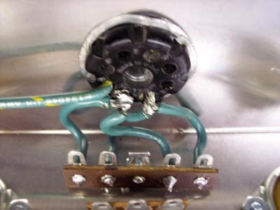
Cut and form two more pieces of the leftover wire to connect the other two lugs to the heater wires such that the pair of lugs on each side are connected to opposite sides of the heater supply as shown in the photo above. At the plug end hook the wires over the bare portions of the wires where they come out of the plug. At the other end solder the wires into the eyelets of the terminal strip. Do not cross these wires.
Connect the pair of lugs on the left to the tubes on the left and the pair on the right to the right tubes. Do not daisy-chain the wires to the EL34s. Run a twisted pair from the H H terminal strip to each tube socket individually. You will have to stop and make more twisted wire as 4 feet won't be enough.
Run another twisted pair from the terminals to the 6CG7 socket. It is acceptable to daisy-chain from there to the two 12AX7s in turn. Install the 150 ohm balancing resistors on the H H terminals and solder all connections. With so many wires in each lug be very careful not to miss any of them.
Install the ground wire as follows.
It is a number 14 solid copper wire with the insulation removed. It begins at the terminal strip near the back which has the labels B+2, B+3, C-, and C+. This is the only point where the ground wire connects to the chassis. The last piece of leftover transformer wire goes from the center lug, ground, lug of this strip to pin 7 of the power socket. The number 14 wire runs forward through one lug of a terminal strip and ends at the next one to the front. Position this wire above the chassis on a level with the terminal strip lugs it solders to. Another number 14 wire runs transversely, at right angles, to the first one ending at the terminal strip on each side. Also position this wire above the chassis. After cutting the transverce wire to length with a little to spare, feed it under the front-to-back wire and pull the ends up forming a U with the front-to-back wire at the bottom and inside the U. Cross the ends over and pull them down forming a loop. Pull on the ends with two pairs of pliers to reduce the size of the loop. Finally squeeze the loop with a pair of needle nose pliers until it fits tightly around the other wire. Feed the ends through the terminals at each end and straighten it out to look neat. Solder it at the center using plenty of heat. At each end solder the wire to the lugs and cut off any excess length.
Add the two wires that go out to the edges of the chassis. Where one ground wire makes connection to another one form a hook in the end of the wire, crimp it around the first wire and solder. Be sure to use plenty of heat. Ordinary pieces of hookup wire connect from the ends of the transverse wire to the center, wiper, lug of the AC balance pots. Two more pieces of number 14 run from near each end of the transverse ground wire to the terminal strips just behind the input level pots. The wires continue on to the two terminal strips near the left and right edges of the chassis.
Use ordinary hookup wire to make connections from the power plug to the terminals as labeled in the drawing. They are B-, B+1, B+2, B+3, C+, and C-. B- connects to the ground wire where it is connected to the chassis. Refer to the schematic diagram for the pin numbers on the power plug.Something NOT to do.
The second terminal strip from the front, in the center, has two purple resistors shown mounted on it. These are the 1 ohm current sensing resistors. DO NOT INSTALL THEM NOW. You will be instructed how to calibrate their values on the Initial Tests and Adjustments page. Also do not install the wires going to the 4 banana jacks in the center front area.I think that covers everything that is not shown or might not be clear in the drawing.
- Introduction.
- Power Supply Schematic and Circuit Description.
- Amplifier Schematic and Circuit Description.
- Power supply chassis layout.
- Amplifier chassis layout. (You are here.)
- Initial tests and adjustments.
A foolish man dreams of wealth,
a wealthy man dreams of wisdom,
and a wise man dreams of tubes aglow all in a row.
Amplifier Smorgasbord.Or use your "Back" button to return to where you were.
This page last updated April 3, 2006.