
To be or not to be?
As I said in the introduction to this series my best boyhood friend, Carl, and I used to call these radios suicide boxes. Most people who owned and used them were blithely unaware of the danger. I'm sure it must have cost some of them their lives. One side of the power line connects to the chassis. Depending on how it happens to be plugged in the chassis could be "hot" 120 volts above power line ground. Most of them have the switch in the chassis side of the line which means that even if you have it plugged in correctly, when you turn the switch off the chassis will be electrically hot. With these units there is no right way to plug them in.A Change For Safety.
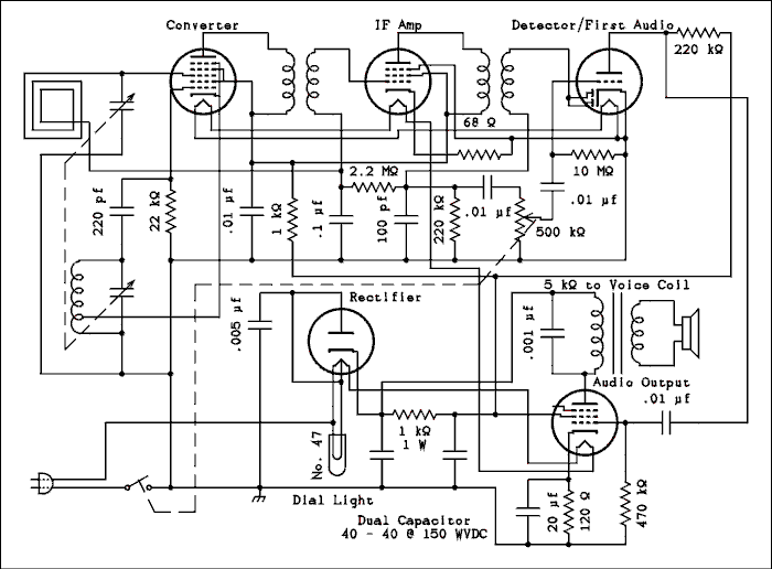
Here is how most AA5s have the power switch wired.

For a verbal description of newly added parts click here.
For a verbal description of the complete diagram click here.
The common wiring method had one side of the line cord going to a pin on the rectifier tube and the other side going to one terminal of the on/off switch. The other terminal of the on/off switch went to chassis.Suppose you plugged it in so the chassis was "cold" when the radio was turned on. That would mean that the bottom prong of the plug was connected to the power line neutral. Everything would be fine until you turned the radio off. Now the top prong of the plug is connected to the hot side of the power line. The tube heaters are cold and have a very low resistance (very approximately 100 ohms). This resistance is connected from the hot side of the power line to the chassis of the radio. You could connect a clip lead from the radio chassis to a water pipe and the radio would come on and play. If part of your body should complete the circuit instead of a clip lead you might never play again.
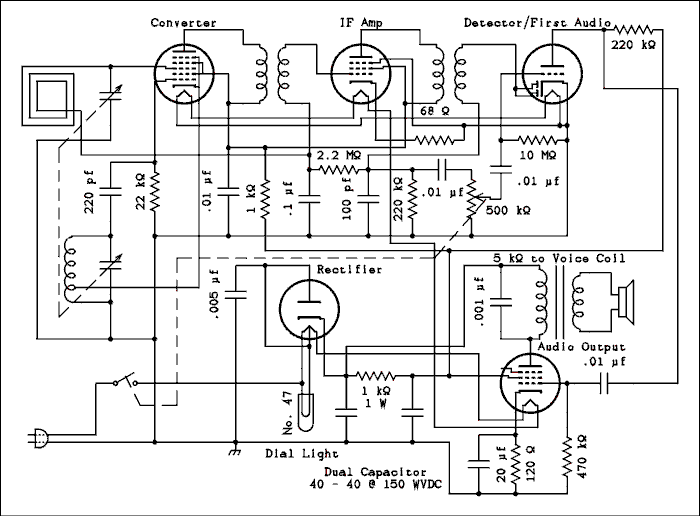
I strongly urge modification of the radio circuit to make it somewhat safer. Here's the diagram.

For a verbal description of newly added parts click here.
For a verbal description of the complete diagram click here.
Before starting to modify the radio go to a discount store and buy a polarized 2 prong plug extension cord. They are usually a dollar or less. Cut away the old power cord but leave short pieces of it on the rectifier tube and switch. If the insulation is in good shape (not always the case in these old sets) leave enough wire to reach to the switch. If the insulation on the old cord is rotten replace it with a piece of wire cut from the extension cord. Decide how long you want the new cord on the radio to be and cut the cord that length from the plug end. You will most likely never find a use for the socket end so cut off the extra cord, save it, and throw the socket end away. Thread the new cord in through the chassis hole. Position the end of the cord near where it is to be connected, the on/off switch and rectifier tube. Leave enough extra to be sure it will be long enough after being secured.Secure the new line cord in the same manner that the old one was, for example tying a knot in it. Separate the two wires for a couple of inches, and strip about 1/4 inch of insulation off the ends of the wires. Twist the fine strands of wire tightly together and melt a small amount of solder over them to hold the strands together. This is known as tinning the wire.
Now remove the wire connected from one side of the switch to the chassis. Strip and tin the piece of wire connected to the rectifier tube socket. Connect this wire to the terminal of the switch you just removed the chassis grounding wire from. Solder the wire in place.
Remove the piece of old line cord from the other terminal of the switch. Solder the wire coming from the NARROW prong of the new line cord to that terminal of the switch.
Solder the wire from the WIDE prong of the new line cord to the chassis connection where the switch used to be grounded.
This will make the radio much safer to work on but the safest way to work on these sets is to obtain and use an isolation transformer. The minimum you need is a 30 watt transformer. A higher wattage unit would give you more flexibility. It may cost you some money but how much is your life worth. If you think you are immortal or just want to live dangerously there isn't much I can say to you. If you decide to work without an isolation transformer get one of those small night lights and permanently connect one side of it to the power ground and terminate the other in a test wire. Touch the wire to the radio chassis. If the light lights up reverse the plug. Test it with the switch off. If there is no right way, plug the radio into a plug strip with a switch and use that to turn the radio on and off.
Jim sent me an email in which he makes the following recommendations.
"These are excellent suggestions. However, I would suggest taking these steps further, by providing a ground fault interrupter (GFI) outlet for powering the radio. These outlets are often found in bathrooms. If the radio is to stay in one place, the outlet that the radio plugs into can be replaced with a GFI outlet. However, replacing the outlet requires electrician skills. Furthermore, the radio may get moved, and the GFI outlet requirement forgotten at the new location. A better solution is a GFI power strip or cord set. The radio could be plugged into the power strip or cord set and the plug held permanently in place, perhaps by tie wraps. The plug would not even need to be replaced by a polarized plug if the existing plug is deliberately inserted with the correct polarity.I did some initial checking and GFI power strips are available from aquarium suppliers. I don't know how readily available the GFI strips are at aquarium stores or how much they cost. Also, hardware stores may have the GFI power strips. I found that Leviton makes a GFI cord set. This is just a cord with GFI box and a single outlet.
In my own case I repaired an AA5 radio which used a capacitor between the metal chassis and one side of the line cord. I found about 120 volts DC between the radio internal ground and chassis. I traced the problem to continuity between the audio output transformer's primary winding and its frame. The radio played well despite this problem. I remounted the transformer with insulated fasteners and spacers. GFI would have protected humans from electrical shock if I hadn't fixed the problem, or if the problem developed later.
Jim"
In a follow-up email Jim added;
"I believe I have found a better solution to the problem of providing GFCI protection for AA5 radios. In my research, I find that many hair dryers are equipped with cords that have plugs containing the GFCI protective device. I found used hair dryers in second hand stores selling for under $5 each. So, the lowest cost plan would be to purchase a used hair dryer with a good cord and GFCI plug, remove the cord and use it to power an AA5 radio, in one of two ways:The simplest way to power the radio is to make the hair dryer cord into a GFCI extension cord. Purchase, from a hardware store, an outlet that installs on the end of a cord. Then, properly wire and attach the outlet to the hair dryer cord and you have a GFCI extension cord. Plug the radio into your GFCI extension cord and plug the GFCI extension cord into AC power. Secure the radio cord into the extension cord outlet, since you want the extension cord permanently connected.
The other way is to use the hair dryer cord to replace the cord that came with the radio. If you choose this method, note that the hair dryer cord is thicker than most AA5 radio cords. The entry hole into the chassis may need enlargement and the strain relief may require replacement to fit the larger cord.
Look for hair dryers with plugs that have two buttons labeled TEST and RESET. If an outlet is available in the second hand store, test for proper operation of the GFCI before buying the hair dryer.
Hair dryers have been manufactured with GFCI plugs for over 10 years now, but not all models have GFCI plugs. Therefore, check very carefully to be sure you purchase a hair dryer with a GFCI plug. GFCI plugs may also be found on hair curlers and other bathroom and kitchen electrics, so check those as well if you can't find a suitable hair dryer.
Jim"
Testing tubes.
You don't necessarily need a tube tester. All you need is a functioning radio that has the same tube lineup as the one you're working on. In the process of testing tubes whether it's with a tube tester or another radio, NEVER PUT A HOT TUBE INTO A COLD RADIO OR A COLD TUBE INTO A HOT RADIO. What the heck do I mean by that? Here is the hot tube into a cold radio scenario. The radio you are working on lights up but doesn't work. You turn it off and take out one of the tubes to test it. You find the tube to be good, yank it out of the tester or other radio, plug it into the radio being repaired and turn it on. The heater of the tube you just switched is hot but the heaters of all the other tubes in the radio are cold. The resistance of the cold heaters is quite low while the resistance of the hot heater is close to its operating value. In the series heater circuit the highest resistance gets most of the voltage. For a few seconds the hot heater will get almost all of the line voltage. It may burn out before the other heaters warm up and start taking their fair share.The cold tube into a hot radio goes like this. You have a complete set of AA5 tubes you know to be good and decide to substitute them in to a defective radio one at a time. You turn off the radio, remove one tube, replace it with one of the same type number and turn the radio back on. The cold heater won't take its share of the voltage for a few seconds. The other tubes will proportionally divide up the over voltage until the cold one warms up. If the one you plugged in cold is one of the 12 volt tubes the chances of doing serious damage are small but still exist. If the cold one is the 35 or 50, the other tubes are going to get quite a large over voltage shot and at least one of them may not survive.
The Dial Light
As you learned the dial light carries the B+ current. When you first turn the radio on the light glows at normal brightness for a fraction of a second and then dims down. As the tubes warm up and the radio begins to play the light comes back to normal brightness. If you turn the radio off and right back on the light will light up very bright for a fraction of a second and then dim back to normal. You don't have to do this many times before the light burns out. SO DON'T DO IT.If the light burns out the voltage across that part of the heater of the rectifier tube will go up to about 12 volts. That portion of the heater will over heat and will burn out within a few hours of operation. Since dial light bulbs are much cheaper than rectifier tubes, don't operate a radio with a burned out dial light. If you have a large collection of AA5s you should keep some spares on hand.
Trouble Shooting Hints.
The most common defect of these radios is a bad filter capacitor. This is the one I have designated in the diagrams as a dual 40 microfarad at 150 volts. In real radios it could be as low as a dual 20 microfarad. The symptom is a loud hum that may be changed slightly, if at all, by the volume control. Sometimes you can tune in a station and hear it through the hum. The only thing for this is to replace the capacitor. One with this failure mode can't be reformed. You can go up in capacitance or voltage but not down. For example if the radio has a 20 - 20 microfarad at 150 volts you could replace it with a 20 - 30 at 150 volts or 40 - 40 at 250 volts.If you have a radio which lights up but has no sound try this. Touch the tip of a screwdriver to the center terminal on the volume control while touching the metal part of the screwdriver with one finger. There are two terminals on the back of the control, these are the on-off switch. You don't want to touch them! The terminals of the potentiometer are in a group of 3 and are on the side of the control. Turn the volume to middle or higher. Touch the screwdriver to the terminal and touch the metal shaft of the screwdriver with a finger. You may or may not hear a loud hum or buzz. If you do the audio section is working and the trouble is in the converter, IF or detector. If you don't hear anything the trouble is in one of the two audio tubes. Not necessarily the tubes themselves.
Use a DC voltmeter to measure the voltages on plates and screen grids. A leaky capacitor can put a positive voltage on the control grid of the 50L6/50C5.
If the audio section is working, try scratching on the grid terminal of the IF tube with the screwdriver. If you hear static the IF amplifier is OK and the trouble is most likely in the converter.
Check to see if the oscillator is running. The oscillator grid of the converter tube should have a negative voltage on it. A VOM won't work here. Use one of those cheap DMMs. Wind one lead of a 1 meg ohm resistor around the measurement probe. Touch the other lead to the oscillator grid terminal and read the voltage. The purpose of the resistor is to keep the input capacitance of the DMM from stopping the oscillator. You should read anything from about -2 volts to -50 volts. The reading will be about 10 % low but you're not going after precision, you just want to know if there is a negative voltage indicating that the oscillator is running.
If you are using an authentic VTVM you don't need to use the resistor. The DC probe on most VTVMs has a 1 meg ohm resistor built in and the meter calibration takes this into account.
Variations on a Familiar Theme.
There are variations on the theme of the All American 5. One is the portable. The numbers of all but one of the tubes begins with the number 1. The other is a 3V4. The numbers are like 1R5, 1U4 and 1U5. They usually have an RF stage which you can spot because the variable capacitor will have three sections instead of two. Rarely is there a rectifier tube. If there is its number begins with 117. Most portables used something called a selenium rectifier. Many old portable radios I have seen have had them replaced with silicon rectifiers. If the guy who did the replacing wasn't well informed, he failed to add an additional voltage dropping resistor and the filaments of the tubes will be running over voltage. The filaments in portable radio tubes have to run from DC so they operate from a resistor on the DC power supply. They are usually in series.As I noted earlier there was an All American 4 which didn't work very well and an All American 6 which worked very well but cost more. Sometimes the 35Z5/35W4 would be replaced by a selenium rectifier. If you get one of these go ahead and replace it with a silicon. The extra voltage won't hurt anything in this case.
That's all folks.
Previous; The Audio Section.Or use your "Back" button to return to where you were.
Thank you for visiting my page at Angelfire.
Please come back and visit again!This site begun March 14, 2001
This page last updated June 27, 2010.