Many decades ago someone gave me a bunch of Sam's Photo facts. I learned a lot by studying the schematic diagrams contained there in. But one thing had me stumped. There were a couple of P A amplifiers and although they had the usual 4 8 and 16 ohm outputs there was a fourth output labeled 70 volts. It didn't make any sense to me. The voltage at the output would depend on how high the volume control was turned up. I asked my buddy Carl but he didn't know either. I asked another mutual friend and he didn't know but he made up an answer that didn't make any sense at the time and still doesn't. Several years later I learned the answer and after understanding set in, it made perfect sense.
70 Volt Line Systems.
The 70 volt line system was devised to permit relatively high impedance transfer of power over a wide spread P A system and at the same time allow different speakers in the system to receive different amounts of power. A P A system can't be set up with all the speakers in parallel.If you have a small system say in a church with 8 speakers each with an impedance of 8 ohms the combined impedance is 1 ohm. That might be doable although some heavy wire would be required. But suppose you had a system in a shopping mall with 100 speakers. There's no way you are going to drive the 0.08 ohms of that system with any sort of practical amplifier, be it tube or transistor.
And then there is the problem of getting different volume levels at the various speaker locations. Speakers in the concourses need to play at a higher level than speakers in individual stores. You may have thought of using speakers of different impedance levels but such speakers would have to be ordered to match the design and if someone made a wrong decision another speaker would have to be ordered at some considerable expense. Then if the mall is expanded and more speakers need to be added it means the original system must be scrapped and redesigned from scratch.
The 70 volts comes from the fact that the output transformer is designed so as to provide 70 volts RMS when the output stage is operating at full power. This is true whether the amplifier has a maximum rated power of 15, 150, or 1500 watts. Not only that but the amplifier has been designed with a large amount of feedback so the 70 volt output is a voltage source. Think of it as a regulated power supply that has a large number of loads connected to it. As long as it is not overloaded it will maintain a constant voltage and will deliver as much current as the total of all loads demands. Impedance matching doesn't enter into it. Each load takes only what it needs. In a system which is being expanded over time the amplifier will be lightly loaded at first but as the number of speakers increases it will have to deliver more power. One day it will be overloaded and will have to be replaced with a larger one.
Obviously a transformer is necessary at each speaker location to step down the voltage for a match to the speaker. A typical transformer has several taps on both primary and secondary. A table that comes with the transformer or is supplied in a manual from the manufacturer will list the power levels that will be provided to the speaker with a particular combination of taps. For example the transformer can be set for 1 watt. This means that if the line has a 70 volt sine wave on it the speaker will get 1 watt. This is independent of the other transformer/speakers on the line and the power of the amplifier. The amplifier always puts 70 volts on the line at it's maximum power and each speaker takes the power level that has been set by the installer. Naturally the voltage on the line is going to be dependant on program content so the speaker will never see an average power of 1 watt.
The beauty of a 70 volt line system is its flexibility. For example if a particular tenant decides the music in his store is too loud, the entire system does not have to be redesigned. A mall technician can change the taps on the transformers in that store to lower the volume. A volume control pot is also an option permitted by the relatively high impedance of the system. Designers don't like them because if everybody on the line has one a considerable amount of power will be wasted requiring a more powerful amplifier. If the mall is expanded the existing part of the system does not have to be touched. The new areas can just be added to the line and the original amplifier replaced with a more powerful one.
My Personal Experience.
Several years ago a couple of 25 watt Executone 70 volt amplifiers followed me home and after some discussion Sue agreed that I could keep them. I hooked them up with two pairs of speakers, a pair of Realistic Nova 7s and a pair of Sony APM speakers that had been designed for use with component TV, now called home theater, systems. The two speakers complemented each other nicely each one filling in the deficiencies of the other. However, they needed to operate at different levels. With the 70 volt amplifiers, no problem. All I had to do was connect different taps on the transformers.You probably don't think of such a system as being high fi but the amplifiers check out as having a frequency response of below 10 to 30,000 Hz plus or minus 3 dB. I have to say plus or minus because there is a 3 dB peak at 20,000 Hz. This peak will be dealt with later. Also eventually I will run a frequency response on the complete system of amplifier and line transformer and measure the distortion.
The following section goes into some detail about the amplifiers and the necessity of replacing one of the output transformers. If you want to stop reading here it's alright with me.
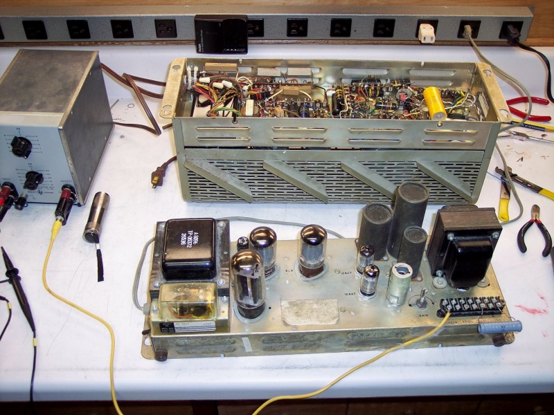
The Executone Amplifiers.
Figure 1 Executone 70 Volt Amplifier.
This is by no means a complete schematic. Obviously it has a power supply but it also has a delay relay that keeps the amplifier muted until the tubes have warmed up. There are also provisions to allow the amplifier to be muted by an external signal. Muting is accomplished by opening the ground connection to the output tube cathodes not by turning off the B+.
One of the first things you are likely to notice is that there is no pot for adjusting the bias on the output tubes. The usual reason a manufacturer will make this design change is to save money. If it had an adjustment someone on the assembly line would have to be paid to adjust it. But this is no bargain priced piece of equipment. I think the real reason was to prevent mal functions and possible damage by an uninformed person tinkering with the adjustment. If there is no pot to turn some mall employee who thinks he knows what he's doing can't get it out of adjustment.
The first triode, 1/2 12AU7, has a 10 k ohm grid stopping resistor and the 6L6s have 4.7 k ohm stopping resistors. You may think I made a mistake in the case of the second triode, half of the 12AX7. Apparently the 12AU7 stage has too much gain and a little had to be thrown away. As you will see farther down the page this amplifier has a lot of gain even with the feedback loop closed up.
Impedance Calculations.
Now I'm going to totally confuse the issue by making impedance calculations. To avoid being confused you must understand that any impedance calculations are unique to this amplifier. If this were a 50 watt or 150 watt amplifier the calculated impedance values would be completely different.This is a 25 watt amplifier. To reiterate, the amplifier when optimally loaded will deliver 25 watts and the output will be 70 volts. The optimal load is given by,
R = V2 / P = 702 / 25 = 196 ohms. That means if we connect a 196 ohm 25 watt load resistor and turn the amplifier up until the output is 70 volts it will be delivering 25 watts. Is that stating the obvious? But if the resistor is removed the amplifier's output voltage will only increase by a small amount and it won't be damaged. These amplifiers are designed to be unconditionally stable. Unconditional stability means it won't oscillate for any load condition. A 1 watt load will present a load impedance of 4900 ohms. This amplifier will power 25 speakers that have their transformers wired for 1 watt.
Note that there are two other outputs, 20 volts, and 3.5 volts. The impedance for these is
R = 202 / 25 = 16 ohms, and
R = 3.52 / 25 = 0.49 ohms.
The 20 volt output could drive a 16 ohm speaker directly. I have a couple of Electro Voice 12TRX-B speakers which are 16 ohms. This may be my excuse to build enclosures for them. The 3.5 volt output could drive up to 16 8 ohm speakers. The Current is only 7 amps but fairly heavy wire would have to be used, at least near the amplifier so the wire resistance would be small compared to the low impedance of the combination of all speakers.
Frequency Response.
From here on we will build on the knowledge found at Amplifier Compensation. There are some complications that may make the data seem as if it has been cooked. If you try to make calculations based on the data they won't come out right. 1) You will have noticed that the feedback is taken off of the 20 volt tap on the output transformer rather than the 70 volt tap. I can't say why. 2) Furthermore there is a stage of gain ahead of where the global feedback loop begins. This stage with the attenuator that follows gives an overall gain of 17 dB. 3) And just to make things more interesting the Syscomp device will not run an analysis if its signal generator output is below about 5 % of maximum. Because this amplifier has so much gain I have inserted an adjustable attenuator between the signal source and amplifier. It is set to 30 dB. The Syscomp has a maximum input voltage of 50 volts peak. Presumably this means 100 volts peak to peak but the 70 volt line output has a peak value of approximately 100 volts. To avoid blowing my newest toy I am using a times 10 probe on the B input. The A input is connected via a T to the signal source and the input of the amplifier through an attenuator.Loop Gain AB.
Only number 1 above applies to the measurement of loop gain AB. The wire from the 20 volt tap has been unsoldered from the 12 k ohm feedback resistor, signal injected at the resistor, and output taken from the 20 volt tap.

Figure 2 Loop Gain with 4.9 k ohm load.
The load on the 70 volt tap is 4.9 k ohms.
The scope probe is connected to the 20 volt tap.Peak gain is 28.0 dB at approximately 1000 Hz.
Phase crosses 180 degrees at 780 Hz.
Gain crosses 0 dB at 10.5 Hz and 23.3 kHz.
Phase angles.
-45 at 6.8 Hz
-135 at 116 Hz
+135 at 2.35 kHz
+45 at 12.4 kHzThis is the ideal loop gain response which will allow the greatest amount of feedback and still be stable at both the low and high ends. This is counter intuitive but The rest of the response curves will show that it works.
Now lets calculate the gain with a 4900 ohm load. First converting gain in dB to voltage gain.
BAv = 10dB/20 = 1028/20 = 25.119 This is the value of BA. But,
B = Rk / (Rk + Rf) = 330 / (330 + 12000) = 26.764 x 10⁻³ Now Av = BAv /B = 25.119 / 26.764 x 10-3 = 938

Figure 3 Loop Gain with 500 ohm Load.
Load is 500 ohms.
Peak gain is 14.1 dB.
Phase crosses 180 degrees at 738 Hz.
Gain = 0 dB at 21.5 Hz and 18.7 kHz.
Phase angles.
-45 at 6.7 Hz.
-135 at 95.5 Hz
+135 at 3.87 kHz
+45 at 61.4 kHz
Now lets calculate the gain with a 500 ohm load. First converting gain in dB to voltage gain.
BAv = 10dB/20 = 1014.1/20 = 5.0699 This is the value of BA. But,
B = Rk / (Rk + Rf) = 330 / (330 + 12000) = 26.764 x 10⁻³ Now Av = BAv /B = 5.0699 / 26.764 x 10-3 = 189
The load makes quite a difference. However, the closed loop gain only changes by 1 dB as the open loop gain changes from 938 to 189.
From the data above we can construct the Bode diagram as we have done for other amplifiers.

Figure 4 Bode Plot for Both Values of Load.
Interesting how the corner frequencies are effected by the load. I didn't expect that. My experiments, which were not all presented here, indicate that the amplifier was optimized for a 500 ohm load which was why I selected it. From the Bode plot alone I would expect the amplifier to be unstable for a 4900 ohm load. The slope breaks from -1 to -2 at 13.5 dB of gain. Apparently what saves it is that the phase flattens out instead of continuing in a straight line as theory would predict. Sometimes it seems as though electrical engineering is mostly a science but there are times when it becomes a black art.
Closed Loop Gain.

Figure 5 Closed Loop Gain with 4.9 k ohm Load.
You may be wondering how I could come up with the dB and frequency values with such accuracy. The program provides a cursor that reads out the values of gain and frequency or phase and frequency where it is located. I read the values while the program was live and typed them in. In this figure the attenuator shown in the photo above was in use and set to 30 dB. The values read from the graph have been corrected by this amount. Also remember that the loop gain was graphed with the output taken from the 20 volt tap while the closed loop figures are at the 70 volt tap. That is a difference of 10.9 dB.
(direct readings) [Corrected for Attenuator]
Flat part of gain (31.3 dB) [61.3 dB]
Peak of 5 dB at 23.3 kHz
-3 dB below flat portion at 6.9 Hz and 37.3 kHz.

Figure 6 Closed Loop Gain with 500 ohm Load.
Flat part of gain (30.3 dB) [60.3 dB]
No peak.
-3 dB points at 7.3 Hz and 29.1 kHz.
Applying a Little Lead Compensation.
My first thought was to start the rise of the lead circuit at 12.4 kHz where the phase for the 4900 ohm load indicates a break from a slope of -1 to -2. This gives a capacitor of 1.0695 nf. A 0.001 uf capacitor was soldered in parallel with the 12 k ohm feedback resistor. I think you may be getting a little tired of looking at this Syscomp screen shots. I found in trials not shown that this was too much of what is usually a good thing. The peak went away with a 4900 ohm load but with a 500 ohm load the upper end was severely limited. It appears that some compromise is in order. I may find that the original designers already found that compromise.Instead of trial and error I decided to try using the -1 to -2 breakpoint from the 500 ohm load data. The capacitor came out to 216 pf. I soldered a 220 pf cap across the 12 k ohm resistor and found the following results.

Figure 7 Closed Loop Gain with 4900 ohm load and Lead Compensation.
Flat Part of Gain (31.3 dB) [61.3 dB]
Peak of 1.7 dB at 16.7 kHz.
-3 dB from flat part at 5.2 Hz and 19.2 kHz.

Figure 8 Closed Loop Gain with 500 ohm load and lead compensation.
Maximum Gain 30.0 dB No peak. -3 dB at 6.8 Hz and 23.3 kHz.
Yes dear friends, it is true. Electrical engineering is mostly a science but there are times when it becomes a black art.
The Other Amplifier.
I'll bet you thought the page was coming to an end. Well, think again. The second of the two amplifiers has a problem because the output transformer has been replaced.The Back Story.
There were originally 3 Executone amplifiers. One didn't work and I found it had an output transformer with an open primary. I parted it out and kept the parts for any future repairs of the two that worked. Then one day while I was in the middle of a mix one channel went dead. Yes, these amplifiers also served as studio monitors. The problem turned out to be, guess what, the output transformer. I figured my monitor system was finished but luckily I found a Hammond 1645 which has a 70 volt tap. Considering the history I ordered two and when they came in I put one in the drawer and the other in the amplifier. I was in a hurry to get back to my mix project so I didn't take a lot of time to figure things out. I didn't know that the 16 ohm tap could substitute for the 20 volt tap. I scaled down the feedback by changing the value of B and closed up the loop to the 70 volt tap. A square wave test showed a lot of ringing so I soldered a 390 pf capacitor across the feedback resistor. That tamed it and I put it back together and that's how it has stayed for maybe 15 years?

Figure 9 Amplifier 2 Loop Gain with 4.9 k ohm Load.
Load 4.9 k ohms.
Peak Gain 29.7 dB
Phase crosses 180 at 698.2 Hz
Gain = 0 dB at 6.64 Hz and 28.3 kHz.
Phase.
-45 degrees 6.19
-135 degrees at 87.9 Hz
+135 degrees at 2.23 kHz
+45 degrees at 12.0 kHz.

Figure 10 Amplifier 2 Loop Gain with 500 ohm load
Load 500 ohms.
Peak Gain 19.0 dB
Phase crosses 180 at 625.2 Hz.
Gain = 0 dB at 9.12 Hz and 32.95 kHz.
Phase.
-45 degrees at 4.45 Hz
-135 degrees at 56.5 Hz
+135 degrees at 4.21 kHz
+45 degrees at 30.8 kHz
This doesn't seem very different from the first amplifier. I have returned the feedback to its original configuration, in fact I did that before running the curves above. Lets go ahead and close up the loop to see what we have.
Closing the loop.

Figure 11 Amplifier 2 Closed Loot Gain with 4.9 k ohm Load
Flat Part of Gain (30.4 dB) [60.4 dB]
Peak of 5.6 dB at 26.8 kHz.
-3 dB below flat portion, 5.1 Hz and 49.2 kHz.

Figure 12 Amplifier 2 Closed Loop Gain with 500 ohm Load.
Flat Part of Gain (29.8 dB) [59.8 dB]
Peak of 0.8 dB at 18.7 kHz.
-3 dB Below Flat Portion, 5.70 Hz and 35.8 kHz.
Adding a little Lead.
Comparing these curves with those from the first amplifier indicate that a little more lead is needed here than was needed there. I decided to try a 270 pf capacitor and didn't need to try another value.

Figure 13 Amplifier 2 Closed Loop Gain with 4.9 k ohm Load and Lead Compensation.
Load = 4.9 k ohms.
Flat Part of Gain (30.6 dB) [60.6 dB]
Peak of 0.6 dB at 19.8 kHz.
-3 dB below Flat Portion at 4.09 Hz and 26.1 Hz

Figure 14 Amplifier 2 Closed Loop Gain with 500 ohm Load and Lead Compensation.
Load = 500 ohms.
Flat part of gain (29.6 dB) [59.6 dB]
No Peak.
-3 dB Below Flat Portion at 5.70 Hz and 25.3 kHz.
The next step is to connect a line to speaker transformer and a resistive load and test frequency response and distortion. But first I need to document the changes I have made in case someone else finds these amplifiers useful after I have gone on to that great electronics shop in the sky.
The matching transformers.
Several transformers came with the amplifiers. Since I don't have any manufacturers data on them I'll have to ring them out for myself. Here is how I had them wired. I'll want to put them back like they were if practical.Primaries: Red and Blue to 70 volt line.
Transformer 1 Secondary: Black and Yellow to Sony Speakers.
Transformer 2 Secondary: Black and Green to Nova 7 Speakers.
Input (Blue and Red) 7.23 Outputs. Averaged over two transformers. Leads Volts Turns Z Zp Power on Ratio Ratio 8 ohm 70 V Line load Black and Brown 0.3185 22.70 515.3 4.122 k 1.189 W Black and Yellow 0.454 15.92 253.4 2.027 k 2.417 W Black and Green 0.637 11.35 128.8 1.030 k 4.757 W Input (Blue and Orange) 7.20 Outputs. Averaged over two transformers. Leads Volts Turns Z Zp Power on Ratio Ratio 8 ohm 70 V Line Load Black and Brown 0.444 16.22 263.1 2105 2.328 W Black and Yellow 0.633 11.37 129.3 1034 4.739 W Black and Green 0.888 8.108 65.74 525.9 9.317 W
Transformer Data.
Input to Blue and Red leads = 7.23 VAC.
Secondary
LeadsSecondary
VoltsTurns
RatioImpedance
RatioImpedance
For 8 Ohm
LoadPower from
70 Volt Line.Black & Brown 0.3185 22.70 515.3 4122 1.189 Black & Yellow 0.454 15.92 253.4 2027 2.417 Black & Green 0.637 11.35 128.8 1030 4.757 Input to Blue and Orange leads = 7.20 VAC.
Secondary
LeadsSecondary
VoltsTurns
RatioImpedance
RatioImpedance
For 8 Ohm
LoadPower from
70 Volt Line.Black & Brown 0.444 16.22 263.1 2105 2.328 Black & Yellow 0.633 11.37 129.3 1034 4.739 Black & Green 0.888 8.108 65.74 525.9 9.317 Two transformers were connected to the 70 volt line each set to Black - Orange on the primary and Black - Green on the secondaries. An 8 ohm load was connected to each secondary. For the plot below the power was 1.56 watts in each load.
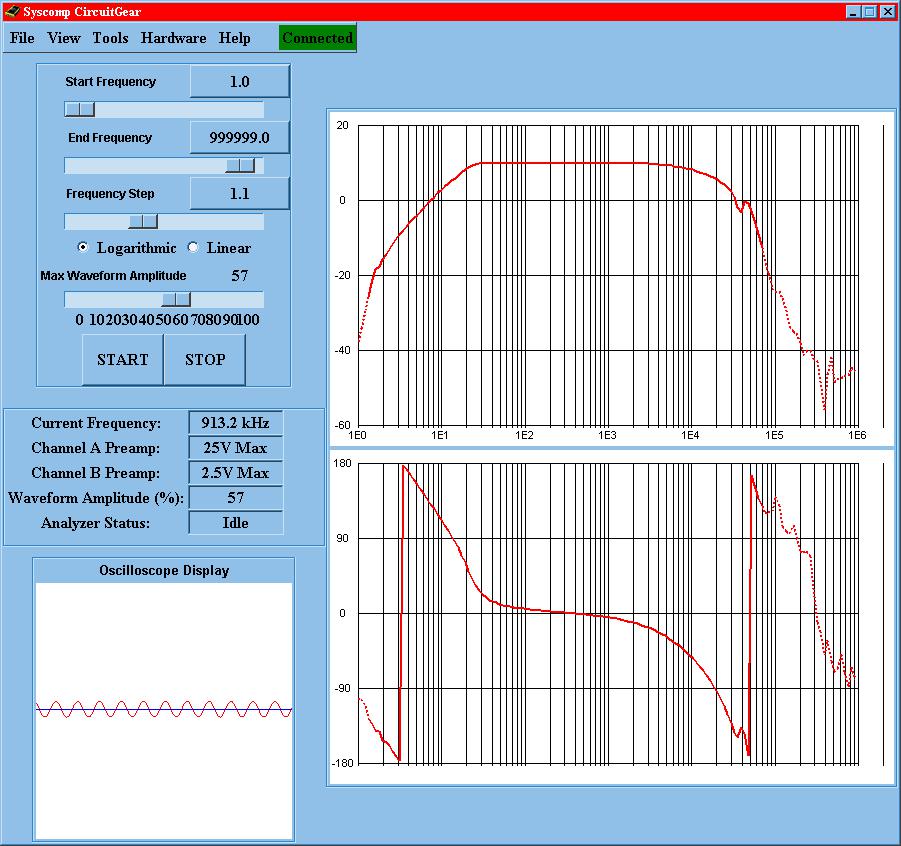
Figure 15 Frequency Response of Complete System.
Flat part of graph = (10.1 dB) [40.1 dB].
No Peak
-3 dB from Flat part at 16.7 Hz and 13.8 kHz.
Down 4.4 dB at 20 kHz. The very low frequencies show considerable hysteresis distortion. Even at 30 Hz some is still visible as shown below.

Figure 16 Scope Display Showing Distortion at 30 Hz.
Total Harmonic Distortion measured at 1000 Hz and 1 watt in each load was 0.074%. I think I can live with this system for quite a while.