____________________________________________________________________
PLASMA TWEETER
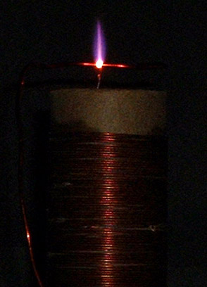
This little electrical discharge (at left) can make a very
loud, and very good, sound. In fact, the "plasma tweeter"
is perhaps the best high-range speaker in existence...and
lacking several thousand bucks to buy it, one can build it
with a few old tubes and other junk. Here I present the
results of much playing around in lab last year- a plasma
tweeter that works rather well.
__________________________________________________________________________________

|

PROJECT DESCRIPTION |
SCHEMATIC & OPERATING DETAILS |
INTRODUCTION Most speakers create sound by vibrating a diaphragm of some sort, which in turn moves the air nearby. The
plasma tweeter has a small electric arc that is amplitude modulated by the audio signal, which causes nearby air to move- and sound
results. Plasma doesn't have the inertia or the resonance problems that cause distortion in diaphragm speakers. So at least in theory,
the plasma tweeter has an edge on just about every other kind of tweeter. The idea of reproducing sound using vibrating discharges
dates back at least to the '60's, when commercial plasma tweeters such as the Ionophone made their debut. These devices
demonstrated the high fidelity of the plasma tweeter and proved that it could be built cheaply; however, various practical problems
also came to light. A few companies make plasma tweeters today and they now carry a huge price tag. Heinrich Ulmann is
responsible for bringing the plasma tweeter to my attention and to that of several other do-it-yourself enthusiasts. His web site is the
best reference on plasma tweeters that I have found. (Use BabelFish to translate the German version.)
PROJECT DESCRIPTION After reading Heinrich Ulmann's web site, I felt that I just had to build a plasma tweeter. Not because
I am an "audiophile" (in fact I knew next to nothing about audio circuitry before starting the project), but because the "coolness factor"
of a flame speaker was too great to pass up. The circuit I designed uses tubes exclusively, because that is what I have on hand. The
fact that the audio stage tubes came right out of an old Tektronix oscilloscope means that they are probably cheap and readily available.
There is one 12AU7A dual-triode AF input stage, followed by a 6CL6 pentode power amp that screen modulates a 6146A beam
tube oscillator. The circuit requires ~725 V high voltage, ~300 V low voltage, and 6.3 V for heaters; see below for more power
supply information. Total power consumption is in the neighborhood of 80 watts. The heart of the tweeter is a 10.0 MHz power
oscillator and "tesla coil" resonator to develop the speaker discharge. All parts are readily obtainable from Hosfelt, All Electronics
or Digi-key. Construction, tune-up, etc. are straight-forward. Making the chassis with a hand drill and scrap metal was by far the
most time-consuming part. This makes a great project for beginners in electronics...just be careful of that B+ voltage!
My Plasma Tweeter. In front are the preamplifier and
modulator; in the rear is the power oscillator and
resonant coil. Also visible are the parasitic
suppresser in the 6146 plate lead and an RF blocking
choke on the B+ lead.
For a power supply, you can satisfactorily use the Heathkit ham radio supplies with +600 V B+, +300 V "Bias", and 6.3 V heater.
I use a homemade 0-900 V / 320 V / 6.3 V power supply that will run just about any other small tube project. "Rat nest"
construction was used. Take care to keep RF circuit leads away from the AF stages; otherwise, some very annoying oscillations
and bad sound results.
Underside of tweeter, showing "rat nest" wiring. I
paralleled capacitors and resistors to get the right
values quite frequently. The AF stages are at the
top of the picture and the 6146 at the lower right.
CIRCUIT
(Click image for downloadable schemat and parts list, zipped Word97 document.)
| C1__10
cm wire loop at top of L1
C2__0.002 uF, 2 kV polypropylene C3__0.001 uF, 2 kV polypropylene C4__0.05 uF, 600 V paper C5__0.05 uF, 1.2 kV paper C6__0.006 uF, 2 kV polypropylene C7__10 pF, 1 kV ceramic C8__33 uF, 16 V electrolytic C9__0.01 uF ceramic C10_0.05 uF, 600 V paper C11_0.1 uF, 600 V paper C12_0.0015 uF, 1 kV ceramic C13_0.0015 uF, 1 kV ceramic C14_33 uF, 16 V electrolytic C15_0.02 uF ceramic C16_47 pF ceramic C17-C20_0.0015 uF ceramic C21_150 pF mica |
R1__47
Ohm, 2 Watt Carbon
R2__21 kOhm, 4 Watt Carbon R3__20 kOhm, 4 Watt Carbon R4__94 Ohm, 1 Watt Carbon R5__8 kOhm, 8 Watt Carbon(s) R6__30 kOhm, 2 Watt Carbon R7__0.5 MOhm pot R8-R9__100 kOhm, 1/2 Watt Carbon R10_490 kOhm, 1/2 Watt Carbon R11_1 kOhm, 1/2 Watt Carbon R12_510 kOhm, 1/2 Watt Carbon R13_0.5 MOhm pot R14-R15_240 kOhm, 1/4 Watt Carbon R16_51 Ohm, 1/2 Watt Carbon |
L1__7
cm long winding of #24 cotton-covered magnet wire, on 3 cm wide cardboard
form (see instructions!)
L2__4 turns #14 wire, over R1 L3__Small pie-wound RF choke, see text L4__Small pie-wound RF choke |
An audio signal (low power, such as from headphone jack) enters at C21 and R16. C21 bypasses RF to ground to keep it out of the
audio source. R16 provides a load for the audio source and is probably unnecessary. C18-C20 and R14-R15 form a high-pass filter
to keep the low frequencies out of the tweeter. Not essential but highly recommended. The pot R13 participates in this filter, having
an audible effect on the frequency response of the filter, but it also controls the volume. The 12AU7A has its triode stages in series for
more amplification. Cathode bias is set by R11; C14 and C15 bypass AF and stray RF, respectively. Output is coupled to the grid of
the 6CL6 via C12. Pot R7 sets the gain for the 6CL6. R6 creates proper screen grid bias and R4 develops the cathode bias. R3 and
R5 are rather critical values, as I have observed. They establish a DC plate voltage of roughly 130 V for the 6CL6 as well as set the
DC screen bias on the 6146. The 6CL6 develops several watts of AF power, almost all of which get burned up in R5. The AF voltage
couples onto the screen of the 6146 through R3 and the C4 AF bypass. When the 6CL6 is driven to maximum conduction peaks by
the AF, voltage on the 6146 screen drops, and thus it is "clamp modulated." L4 tries to block RF from coming back towards the AF
circuits. Its value is not critical. C7 bypasses RF to ground on the 6146 screen. R2 self-biases the tube for class-C conditions when
oscillations build up.
The oscillator itself is the standard one that has always been used in plasma tweeters, and is elegantly simple. The "Tesla coil,"
element L1, is best described as a base-fed quarter-wavelength open stub, which functions like the more familiar parallel
resonant tank circuit as a frequency-determining and energy storing component. It also functions as a transformer. Initially,
it develops a high voltage at the free end and the little brush discharge forms. Then it matches the low resistance of the discharge to the
high resistance of the 6146 plate. Feedback of the proper phase to sustain oscillation comes from capacitive probe C1, which must be
located at the "hot" end of L1. Most other builders use 30 MHz oscillators. I use 10 MHz, although I successfully tested resonators
up to 60 MHz on this system with fair results.
L1 is easily hand-wound, but its particulars are worth noting: do not use shellac, superglue, polyurethane or probably anything
else to hold it in place. Wrap the magnet wire leads through several pinholes in the coil form to secure them. Don't use PVC pipe
for a coil form- especially at the highest frequencies. It is just too lossy. I can't say that cardboard tube is the best thing to use in
general, but it worked the best for me. If your 6146 draws more than 90 mA plate current, as I have figured out, you should first
suspect a coil with too low Q. In normal operation, the coil gets rather warm.
Another point of difficulty for some builders is the B+ choke, L3. Here's some simple advice- don't trust anything with a metallic
core. None of these worked particularly well, and one even caught fire. All of the little pie-wound "old-fashioned" receiving chokes
I tried did the job without a hassle.
I highly recommend including C2; you may (will) want to do a bit of playing around with the discharge, and the thing
is infinitely more dangerous without this blocking cap. The parasitic suppresser is of dubious value. I didn't notice any changes in
performace with or without...but my neighbors, including a major international airport two miles away, might prefer that I use that
suppresser. Leave it in for good measure!
A few pointers-
1. Low frequencies can muddy the tweeter's sound. Set the high pass filter pot accordingly.
2. Best sound occurs at low volume. Cranking up the second stage gain all the way causes severe distortion.
3. If any tube plates are glowing at all, you are exceeding power ratings! Don't ever run a 6146 red hot, and this circuit should
not get the tube this hot. Blue glow on the glass of the 6CL6 is normal.
4. Use only shielded power and AF cables. Cheap coaxial cable works nicely.
5. 6146 plate current should not change more than a few percent on modulation peaks. If your meter needle is jumping all over with
the AF signal, adjust volume or change R3 or R5. Try adjusting the LV high voltage.
6. Try replacing the 12AU7A with tubes of the same base: 12AT7, 12AU7, 12AX7, etc. They all lend different qualities to the
tweeter's performance.
| PLASMA
TWEETER ADVANTAGES
-No moving parts, so no Doppler, inertial, or resonance distortion -Awesome toy, easy to make too -Multi-purpose: freshen the air, melt small flint glass in flame, use to power plasma globes, light up a blunt, etc. |
DISADVANTAGES
-Can start fires -Arc is a veritable nitric acid factory; must be in ventilated area -Extremely inefficient -Causes RF interference -Multiple HV voltages required |
OTHER APPLICATIONS of the PLASMA TWEETER
The plasma tweeter oscillator makes an excellent plasma display driver- and one that could only cost you the price of the tube you make
it with. Here's an example:
 |
 |
On the left is a photo of a 1-liter pyrex balloon flask, containing air and linked by rubber hose to a small vacuum pump and leak valve.
The leak is set so that we have about 0.5 torr at the flask (I have no way to measure pressure besides viewing the discharge, so it is only
approximate.) It is held about 6" from the tweeter, seen to the flask's right. Quick- turn off the oscillator and everything goes dark...
except the gas in the flask, which glows a bright yellow color for several seconds (bad image at right). Why? The discharge is over,
but dissociated nitrogen (single N atoms) remains. As the N atoms recombine with other N atoms and with oxygen, they produce the
"afterglow." The color of the afterglow, and its brilliancy and persistance, have to do with pressure and impurities in the gas. It's really
got to be seen in person to be fully appreciated...