|
|
| |  |
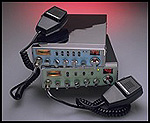
NPC-RC Conversion by Billy D. Ward (AKA The C. B. Doctor) |
|
|
|
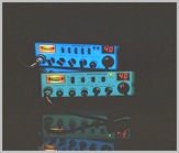
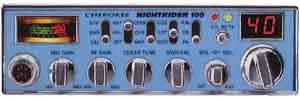
The Cherokee NIGHTRIDER 100 is an AM only C. B. Radio that from the front view appears to be similar to, and has the same measurements as, a Cobra 29 LTD Classic, and it is a 40 channel radio that operates in a frequency range of 26.965Mhz to 27.405Mhz. That, however, is where the similarity ends. The NIGHTRIDER 100 features an Electro-Luminescent back light front panel That the company calls "Radiant-View" with "Lite Pipe" technology for complete illumination of the front. It lights up with what I consider a rather pleasant light bluishglow that appears white when turned off and has a dimmer switch on the front panel. It is the easiest radio to use during night driving. "Clear Drive" circuitry gives you clean and clear transmission and reception and from what I've seen on the bench, it is far superior to Cobra's "Sound Tracker". The "CLEAR DRIVE" SWITCH has three positions to choose from CDS-CDT-NOR. This switch is used to enable the "Clear Drive" audio compander circuit of the radio to provide clear and low noise communications between similarly equipped units. CDS = "Clear Drive System". Makes full use of the Compander feature. elect this when both the transmitting unit and receiving unit are using Compander. CDT = "Clear Drive Transmit". increases the clarity of your transmission when communicating with others not having a Compander. The receiver Compander in the unit will be disabled in this mode to match the non-compressed received signals. NOR = Normal CB Operation without using the Compander.One unusual feature for a regular C. B. Radio is a built-in roger-beep. The biggest advantage that the NR-100 has . . .
is that it will easily accept the Negative Peak
Compression (NPC) conversion, Which in my book makes it a strong
challanger to the Cobra 29 LTD
market! |
|
|
|
|
| This conversion features Negative Peak Compression (NPC) for the modulation circuit which allows the positive RF peaks, during modulation, to be driven in a normal manner to the maximum attainable level prior to clipping (As much as 175% modulation of the positive peak) while compressing the negative peaks to a point below the clipping level (approximately 98% modulation). Therefore, distortion and spurious radiation that is normally associated with deactivating the limiter circuitry is cut to a minimum. Also, modification of the final Rf stage which from a modulated amplifier to a linear amplifier circuit removes a major portion of the current draw through the AM regulator transistor, allowing it to run a significant amount cooler than with a peaked stock final circuit. |
|
|
|
|
| Looking inside for the first time
expecting to find a circuit board similiar to the
board used in the Cobra 29 LTD Classic, I was very plesantly surprised to
see that it has a new board which is very much like a Northstar board that
has been shrunk down to fit a 29 size case. Upon further investigation,I
found to my great atisfaction, that when Wireless Marketing Corp designed
the new line of Cherokee Radios, they kept the circuit as close as
possible to the one that was used in the Northstar Radios making changes
only where necessary to pass the FCC's regulations for legitimate cb
radios. I noticed that there are a lot more surface mount components,
probably due to the crowding of the circuit when the board was shrunk.
The first thing that I noticed that was significantly different about the NR-100 from the Northstars is a heatsink inside the radio on the final RF output transistor which is also a different device. All of the Northstars used 2SC2312's but the NR-100 uses a 2SC1969. If the NR-100 was to pass with the FCC, a 2SC2312 could not be used and they required that the RF final be heatsinked to something that has less ability to to dissipate heat than the chassis. So, they overcame that obstacle by simply mounted an wedge shaped aluminum heatsink behind the final to the inside, back of the chassis which requires leaning the final forward at an angle. Then looking in the area of the AM regulator, I noticed that the driver for the 2SB754 had been changed from a fairly large device, a 2SA1869, to a much smaller TO-92 device, a 2SA1282. The 2SB754 AM regulator is used to modulate the final and the driver instead of using a more conventional modulation transformer. The modulation circuit is similar to a "current pass" circuit used in a regulated power supply where the current is passed through the regulator ("pass") transistor providing the regulated power supply output voltage. The output of the power supply is continually monitored and a "sample" of the output voltage is fed back to the the circuitry that controls the voltage on the base of the regulator transistor, which keeps the output power within a very close tolerence of the desired value. In the AM Regulation/Modulation circuit, There are two voltages present at the base of TR-49, the audio from the microphone preamplifier circuitry, and the DC bias voltage which is adjusted by VR-13 to set the operating point of the AM driver, TR-50 and the AM regulator, TR-51. These two transistors, in turn, supply both the regulated DC voltage and high-level modulation for the RF power transistors TR-43 & 44. The range allowed by VR-13 is fixed by R-237, a 3k ohm resistor, which is connected to the DC supply voltage. This value for R-237 severly limits the range of VR-13. The Northstar radios used a 100 ohm resistor which allowed a considerably larger range for the RF carrier output. The AM/Regulator TR-51 acts like a variable resistor placed in line with the DC voltage to the RF final and driver. When audio coming from the microphone circuit is applyed to the base of TR-49, through R-236 in series with C-187, it is like having the knob of this variable resistor turned back and forth from the center voltage setting at an audio rate. If the audio driver, TR-50 does not supply enough peak audio output to TR-51, the amount of the voltage variation is insufficient to allow the RF output to be modulated to above the limit that the FCC has set for the C. B. Radio service. In the Northstar radios, L-36, the collector choke for the RF driver was simply a solid wire going thru a ferrite bead. In the NR-100 this is replaced by a 2 watt resistor with a ferrite bead slipped over one end. This was required by the FCC so that the voltage to the RF driver would be limited from supplying it's full capability to TR-43, again so that the power would not reach above the FCC limit. So with all of these changes the FCC approved the Cherokee radios for importing into the U. S. as regular cb radios but the radio in this condition will not put out enough power to get excited about. Looking at the PLL circuitry tends to make me think that someone does not want it to be tampered with as it looks like a block of epoxy with a plug on it. I have not attempted to do anything about adding channels to the NR-100 and I don't think that it can be done very easily. However, there is already a rumer that there is a kit that will work to give it the same channels as the "export" radios. Lets get started with the actual conversion . . . . . |
|
|
| STEP ONE Remove the heatsink that is on the RF final
by unsoldering the final along with the heat sensing diodes wires
(D88) which is held against the final within the white nylon shourd
over the final. Take out the two screws that hold the heat sink to
the chassis.
|
| STEP TWO Remove L-36 which is a 2 watt resistor with
a ferrite bead on one lead setting near VR-20. Simply place a plain
wire through the ferrite bead and bend it into a hair-pin shape and
solder it back where you removed L-36.
|
|
|
 |
STEP THREE While you are in this area of the board, you will see that
there are two wires at TP-7 that are in the same hole. unsolder and
pull these two wire ends from the hole. Solder these two ends
together making sure that they do not touch anything and take
special precaution to see that there is no wire or solder still
sticking down though the hole.
|
|
|
| STEP FOUR Remove TR-50 and replace it with a 2SA1869 with the flat side of the device towards the inside of the radio. |
 |
STEP FIVE Remove C-189 and lay it aside for use later on. Prepare a 1N4001 diode (the same kind that is used for the reverse polarity protection diode in almost every radio in existance)by clipping the cathode to 1/8th inch long. Prepare a 100 ohm 1/4 watt resistor in the same manner. Solder the to short ends together. |
|
|
|
|
This completes the conversion. As a precaution, turn VR-13 counter-clockwise before keying mic. Tune and peak RF Procedure to follow: Disclaimer: I do not disclaim anything. If this radio is your own property, as far as I am concerned, you may do anything you want to with it. It is none of my business! |
 |
|