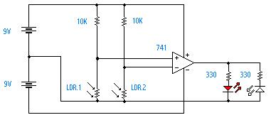
The 741 Op Amp Comparator Circuit
This circuit utilises the 741 Op-Amp in 'Comparator' mode. This allows it to compare two input voltages via two different 'potential deviders'. The potential deviders will devide the voltage between the resistor and LDR. The LDR which has the most light on it will give the largest Voltage output. This can bwe summed up by: If Vout=+7V then LED 1 will light (Vb>Va)
If Vout=-7V then LED 2 will light (Va>Vb)
Therefore if more light is shining on LDR.1 than LDR.2 the left LED will light and vice versa.The reason why 7V is used rather than 9V is because the 741 OP-AMP is not 100% efficient, and 7V is usually outputed instead of 9V. The values of the 10K resistors will determine the sensativity of the circuit, so change these values where appropriate or add two potentiometers in their places.
Parts List
- 1 741 Operational Amplifier
- 2 Resistors- between 1k and 10k
- 2 330 ohm resistors
- 2 LDRs (Light Dependant Resistors)
- LEDs
- 2 9V power supplies
- Bread board or similar
Navigation
Home
Back to intermediate circuits