The bright-field compound microscope is probably the most important instrument you will use in any biology course. Objects such as bacteria, mold spores, plant cells, or animal tissues, too small to be seen with the unaided eye will become highly magnified, thus revealing minute details.Logic would indicate that the more we magnify the image of a cell, the more detail we can see. Unfortunately, this is not true. Light rays passing through curved surfaces are bent. This bending of light produces an enlarged image. But the best research microscopes can currently magnify only 1500 to 2500 diameters. The limiting factor is the nature of light. Of equal importance with magnification is RESOLVING POWER. Resolving power or resolution is the ability to distinguish separate images of objects that fall very close together on the retina of the eye. Since the human eye cannot ordinarily resolve objects separated by less than 0.1 mm, a microscope can extend the resolving power of the eye about 400 times.
In summary, a microscope provides MAGNIFICATION and permits us to see objects as separate images that are close together and would appear as a single object to our eyes.
OBJECTIVES:
This laboratory investigation will acquaint you with the parts of the light microscope and how they are used. You will also learn how to properly maintain and care for the microscope.
The second portion of this investigation will show you how to use the microscope to visualize objects so small that they are almost invisible to our unaided eyes. You will also see various types of cells and some of their internal structures.
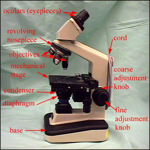
PARTS OF THE COMPOUND MICROSCOPE Check here for a great tutorial on parts and use of the microscope from Davidson College
The following information will serve as an expanded guide to your understanding of the microscope as you view the tutorial. The information is presented as if you had a microscope right in front of you.
- The microscope rests upon the table on its BASE or FOOT.
- Attached to the foot is the upright part known as the ARM or PILLAR of the microscope. When carrying the microscope grasp it firmly by the arm. DO NOT TIP IT. If it is too heavy, support the microscope by holding one hand under the base.
- The STAGE is the platform upon which the object to be studied rests. Our microscopes have mechanical stages which enable you to easily control the movement of the slide you are observing. Below or next to the stage, usually on the right hand side, are two milled knobs. They control the movement of the MECHANICAL STAGE. The inner knob will move the stage toward or away from you. The outer knob imparts a right-left motion to the slide holder. To place a slide on the stage, pull the lever arm that protrudes from the left side of the mechanical stage. This opens the slide holder and allows you to insert the slide into the notched area. Release the lever carefully to avoid damage to the slide.
- The COARSE ADJUSTMENT is the larger milled wheel located near the base of the microscope, on each side. This moves the stage up and down and enables you to get an approximate focus on the study object. About 95% of your focusing is done with the coarse adjustment.
- The FINE ADJUSTMENT is the smaller milled wheel at each side of the base of the microscope. This adjustment moves the stage up and down small distances to bring objects into sharp focus. You should be able to use this adjustment to gain knowledge about the relative position of the parts of the object you are observing. Focusing up and down will bring new parts into clear focus, and tell you that these parts are above or below the parts on which you had pre viously focused. Remember that even though small, objects you are observing are three-dimensional. Thus, they require frequent readjustments of focus. This will aid in develop ment of a clearer concept of the structural relationships between the components of the object. If, in attempting to use the fine adjustment, you find that the wheel has been turned as far as it will go in one direction, turn the coarse adjustment so that the lenses are farther from the object being viewed. Focus again with the coarse adjustment and then turn the fine adjustment. If you have correctly focused with the coarse adjustment, you will not need to turn the fine adjustment more than one half of a turn.
- The REVOLVING NOSEPIECE is at the lower end of the body tube. It normally holds two to four OBJECTIVES. Turn the coarse adjustment so that there is room for the longest adjustment without it touching the stage. Now turn the nosepiece and feel the "click" as each objective goes into place.
Some microscopes have a very short objective which magnifies about 4 times. This is sometimes called the SCANNING objective and can be used to get a wide view of the field of study. The next shortest objective has a large opening in it and a large lens. This objective is called the LOW POWER OBJECTIVE and magnifies about 10 times. In some models of microscopes the number 16 is inscribed in this objective. This indicates that the objective is 16 mm above the object when the object is in focus. The HIGH-DRY objective is longer than the 10 power objective and is identified by the number 40 inscribed on it. It should magnify about 40 times. Take note of these wonderful pictures from SUNY Stony Brook that show the use of the lens mentioned above. Note particularly the cheek cells and the cuboidal epithelium.
The microscopes in many laboratories have an OIL IMMERSION OBJECTIVE. Note the size of the aperture (opening) in this lens. This lens is used by placing a drop of immersion oil on the slide or cover slip. Place the oil exactly where the light is coming through the opening in the stage and onto the slide. The lens is then carefully racked down into the oil forming a continuous column from the slide to the objective lens. Light is not refracted upon passing between the oil and the glass slide. The oil immersion objective magnifies about 100 times. Immersion oil contributes to finer resolution and brightness. These characteristics are most critical under higher magnification. Thus, only the higher power, shorter focus objectives are designed for oil immersion.
For any given lens there is a FIXED FOCAL LENGTH. With the objective in focus there is a cone of light extending from a point on the specimen to the full diameter of the objective lens. Below the specimen is a second, matching cone of light. The base of the cone being the top surface of the CONDENSOR and the apex at a point on the specimen. Theoretically, illumination provides a straight line path for each ray from condensor to objective lens. Immersion oil contributes to the homogeneous distribution of light between the objective and the condensor by having the same idex of refraction as the glasses in the system. These objective lens are PARFOCAL. This means that they are designed so that once you have brought an image into focus under low power, you may switch safely to one of the higher powers without hitting the slide or coverslip or making major readjustments with the coarse adjustment. You will find that the object you are viewing will be in approximate focus. If, when switching to a higher power, you meet resistance, check the slide. You may have an unusually thick coverslip or you may have your slide on the stage upside down. Before you move to a higher power, be sure to place the object to be viewed in the center of the present field of view. Remmeber that as you INCREASE MAGNIFICATION you DECREASE PROPORTIONATELY the diameter of the field of view.
- At the upper end of the tube are two OCULARS or eyepieces. Each contains two lenses. Note that they do not fit tightly into the body tube. This is one of the reasons you are asked to carry the microscope in an upright position. Note that each ocular bears the marking 10X or 10 on the side. This means that it magnifies 10 times. This ocular number, multiplied by the number on the objective, gives the appro ximate magnification obtainable with that objective.
It is very important to locate dirt particles on the lens system and to remove them with lens paper or lens paper moistened with alcohol or glass cleaner BEFORE beginning the laboratory work. If a blur appears, a sharp image of the object cannot be obtained until the cause is corrected. As you look through the oculars, turn them. If the smear turns with the ocular, then the ocular is dirty. If it does not turn, try moving the slide. If the dirt is still present, switch the objectives and see if the dirt is on the objective. If not located at any of these points, clean the condensor and/or the built-in light source. In general, clean all surfaces through which light passes.
- Beneath the stage are a series of lenses which serve to bring the light rays into focus. Known as the CONDENSOR, it may be raised or lowered by turning the milled knob under the left side of the stage (models will vary). To focus the condensor, turn the knob of the light source to a low setting. Note that there is only a small spot of light coming from the light source. Put the microscope on low power (10X objective) and focus the objective lens on the object on the slide. Raise or lower the condensor until a sharp hexagonal shape can be seen through the ocular. The condensor is now in focus for this particular slide. In general, moving the condensor lens away from the stage causes light to be diffused. Moving the condensor toward the stage brings the light to a point on the slide. As you increase magnification you will normally have to move the condensor up towards the stage. Remember, as you INCREASE MAGNIFICATION you also must INCREASE ILLUMINATION.
- Beneath the stage of the microscope, below the condensor, and sometimes attached to the condensor is a series of thin metal leaves which can be opened or closed to regulate the amount of light passing through the lens system of the microscope. This is the IRIS DIAPHRAGM. The iris diaphragm is opened and closed by moving the lever found under the fron-right part of the stage. You should adjust this every time that you look at a new object. This will ensure that you are achieving maximum contrast.
- The light source is built into the base of the microscope and controlled by a rheostat knob or lever.
PROPER USE OF THE COMPOUND MICROSCOPE
- Clean all lens surfaces with lens paper and place the object to be viewed on a slide on the stage of the microscope. Be sure that the 10X objective is in position.
- Adjust the light coming through the microscope so that the object is evenly illuminated and the brightness allows for comfort without squinting.
- Without looking through the microscope, bring the stage up towards the objective until it stops. The microscope should have a built-in stop to prevent damage to the lens system at this magnification. Move the slide so that the object you are viewing is centered in the circle of light coming through the opening in the center of the stage. If no light is present, check to be sure the light source is on, the plug is in the electrical outlet, and the diaphragm is open.
- Look through the oculars as you turn the coarse adjustment and lower the stage until the object is in focus.
- Adjust the iris diaphragm and condensor for good lighting.
- Remember that the objectives on these microscopes are parfocal. Before moving the high-power lens into position, move the object to view into the center of the field.
PRECAUTIONS TO OBSERVED IN USING THE MICROSCOPE
- Never touch any of the lens with anything other than lens paper and approved lens cleaner.
- Always rack down to bring the object into focus.
- Keep both eyes open at all times.
- All initial focusing is done with the COARSE adjustment. Use the fine adjustment to sharpen your final focus and to note the three-dimensional nature of the object in view.
- Always clean the lenses before and after using the micro scope. Be sure to clean all oil from the lens after final use.
- Before returning the microscopes to the cabinet, place the lowest power objective in place. Be sure the mechanical stage is not sticking out and be sure that the power cord is not severely bent at the point where it leaves the base. Recover the microscopes before replacing them in the cabinet.
PROCEDURESAfter you have read about the various parts and functions of the microscope you will have an opportunity to view internet sites with pictures of the materials mentioned below.
1. Compare the position of the image of the letter "e" as seen through the ocular with the position of the printed "e" on the slide. Scroll down this site to find the letter "e".Is it upside down or in the same position as it would be when seen with the unaided eye? Does it appear to be reversed as it would be if seen in a mirror? What happens to the size of the field of view as you increase magnification? What happens to the illumination as you increase magnification?
2. Note the image colored threads;begin your observations starting with the 4X objective and then moving to the 10X and 40X objectives. Scroll down the site to find the colored thread. Notice how the threads overlap one another and thus some parts are out of focus while others are in focus.
3. Examine the images shown under low power (10X objective) unstained; stained with methylene blue. Switch to the 40X objective unstained;stained with methylene blue. Would you describe the cells as spherical, disk-shaped, or neither? Draw one or two cells, including as much detail as you can see. Label all the parts you can identify using your textbook and any other available sources.
4. Examine the onion skin under low power and try to find the boundaries of the cells. Draw a small section of the field of view to show how the cells are arranged.
Note what happens when a drop of stain (iodine-potassium-iodine: IKI) is added to one side of the cover slip. What changes take place as the IKI is spreading across the onion skin? Are specific portions of the cells stained more strongly or darkly than others? Draw and label a single cell at high power (40X).
5. View the images of a culture of yeast cells (Sacchromyces cerevisciae). Examine first under low power and then under high power. Do not be deceived by water bubbles which will appear round with a thick black border. Describe the shape of the yeast organisms.
6.Images of Elodea leaves that have been torn a leaf of this water plant and place d in a drop of water are shown at both low and high powers (100X, 400X)Try to find individual cells. The circular green structures around the edge of the cell are chloroplasts which contain chlorophyll for the process of photosynthesis. Note any structures other than the chloroplasts that are part of the individual cells. Take note of the nucleus and nucleolus of this image.
7. Euglena - these protists have features of both plant and animal organisms. They are very small and can direct their own movement by means of a whiplike appendage called a FLAGELLUM which is located at the front end of the cell. (Check out the great QuickTime movie of Euglena movement). The flagellum will probably be difficult to see. You may be able to see a small orange or red spot near the base of the flagellum. This mass of pigment materials senses light and helps the organism remain near sunlight so it may carry on photosynthesis. See if you can find the chloroplasts. You should be able to see the nucleus.
QUESTIONS
Answer the following questions using complete sentences.
1. What cellular structures do all of the cells and organisms we have seen have in common? What is the function of each of these structures? What structures are unique to plant cells? to animal cells?
2. What is the CHEMICAL PRINCIPLE that allows cells to be stained differentially. In other words, why do certain parts of cells turn a particular color when a dye is added but other parts do not take the stain?
Labelled Photograph of Compound Brightfield Microscope Some Additional Types of Microscopy - A Brief Review
The initial development of microbiology would not have been possible without the ability to see the microbes. From the time of Leeuwenhoek and earlier, crude microscopes were available. In the 20th and 21th centuries the types of microscopes that have been and will be developed has changed dramatically. These new microscopes now have the capability to see individual molecules and even individual atoms. Visit this site to see a comparison of standard light, dark field and phase contrast microscopy.Check out this new site on microscopes - added April 24, 2003. Microscopes Help Scientists Explore Hidden Worlds. This web site, located on the Nobel site, includes succinct information on microscopy, as well as interative simulators. This site provides an excellent model for what is possible on the web. The simulator requires the latest Shockwave Player (free from Macromedia at http://www.macromedia.com/), portraying phase contrast and transmission electron microscopy with surprising accuracy. Single page summaries are available on the history of microscopy, resolution limits, and four types of microscopy: phase contrast, fluorescence, transmission electron and scanning tunneling microscopy. This site is supported by Zeiss. (****) -S
Darkfield - look for picture of Buccal (Mouth) Epithelium
The darkfield microscope uses a modified CONDENSER so that light is prevented from passing directly through the specimen. The light is directed at the specimen from the sides and thus the only light seen is that which is scattered from the cells. This is similar to moonlight. This type of scope makes possible the observation, in the living state, of particles and cells so tiny that they are invisible in a conventional brightfield microscope. The Negative staining technique gives a similar result. This scope might be used for viewing the syphilis organism, Treponema pallidum, a small spiral microbe.Fluorescent
The fluorescent microscope makes use of the fact that certain chemicals and dyes give off light of one color when they are subjected to light of another color (wavelength). A filter in the light source absorbs the fluorescent light so that only the light coming from the organism or molecule comes through to be seen. The dye auromine has been used for TB organisms and gives a yellow light at a wavelength of 600 nm. Fluorescent staining is sometimes done to detect antibodies against syphilis and for detection of the rabies virus. One limitation is that the work must be done in a completely darkened area. A great deal of work in recent times has used green fluorescent protein (GFP) from a jellyfish and luciferin from the firefly for identifying molecules and parts of eukaryotic cells. The photomicrographs of human cheek cells show the use of GFP. It is also being used for extraction and separation of molecules.*Used with permission from Purdue Cytometry. Note the bacteria on the surface of this white blood cell.
Phase-Contrast
The phase-contrast microscope uses a modified DIAPHRAGM to place light out of phase. No staining is required and this scope allows visualization of living, unstained organisms. It is often used with wet mounts and hanging drop slides. It will show motility of organisms and the internal cellular structures will appear as darker, contrasting structures.ELECTRON MICROSCOPY
Transmission Electron Microscope (TEM) Visit the site and note the pictures.
Instead of a visible light source the TEM uses an electrical current to heat a tungsten filament to 20000 C, causing clouds of electrons to boil off around the wire. An Electron gun accelerates the electrons through the vacuum chamber of the scope. Streams of electrons pass through two (2) electromagnets known as CONDENSER LENS. This lens shapes the electron beam so that it passes through the material to be magnified. The material to be examined is mounted on a fine copper wire mesh. The electron beam passes through the material and enters two (2) more sets of electromagnets: the OBJECTIVE LENS and the PROJECTOR LENS. Both of these bend the electron beam and produce high magnification. The extremely short wavelengths of the electron beam are not visible. However, they strike a phosphorus-coated plate, enclosed in a leaded glass for safety. The plate glows and produces a visible image. This is the principle of the picture on a TV picture tube. The operator uses the image on the view plate to position materials and focus the electron beams. He usually exposes a photographic negative from which a photographic print can be made for study. The amount of magnification is determined by the electromagnets used. Magnifications range from 1,400X to 200,000X. The negative can be enlarged several times without loss of resolution producing a final magnification of over 1,000,000X. The major limitations of this technique include: long preparation time of the specimen; a need for very thin slices of the specimen; the use of the vacuum tube means materials must be dehydrated and thus no living materials can be studied.Scanning Electron Microscope (SEM)Visit the site and note the pictures.
This scope was developed as an offshoot of work done during the space program to land a man on the moon. See how a SEM works at this site. Electrons do not pass through the specimen, but scan back and forth across it, allowing a view of the specimen surface in 3-D detail. The electron beam projected from a filament is focused into a fine pencil line by two (2) electromagnetic condenser lens and concentrated on the specimen which is held in a tilted mount. The current from the scanning generator causes this beam to scan back and forth across the specimen while at the same time causing a light spot to sweep across a cathode ray tube where the image will be seen. At this stage the tube looks similar to a TV screen just before the picture comes on. Then the beams that are scanning the specimen are caught by a signal detector and passed through a video amplifier the increases their volume. The signal produced modulates the brightness of the spot moving across the tube and the result is a TV-like image up to 50,000X specimen size. This same principle is used in getting pictures from the moon and other planets.Scanning Tunneling Microscope (STM)
Since the STM was developed in 1981, it has made a dramatic impact on the understanding of surface structures of molecules. It can magnify molecules several billion times. Most biological molecules are too small to be seen with the light microscope and the electron beam of electron microscopes often damages their structure. The STM produces 3-D images of atoms and molecules without the use of destructive electron beams. The microscope works by using a procedure called electron tunneling. A sample must conduct electrons if it is to be imaged with the STM. The samples are coated with metals and the STM detects electrons jumping or "tunneling" from the surface of the specimen. An electrically conductive, needlelike probe, usually made of tungsten, scans the surface billionths of a millimeter above the sample. It follows the sample's surface outline by maintaining a constant distance from the surface. The probe is attached to a computer that projects a 3-D image onto a fluorescent screen. A team of scientists in California recently used the STM to obtain the first direct image of DNA. These new images show the three-dimensional structure of DNA and provide support for theories that DNA exists in several helical variations.