

STEPS OF THE DESIGN

DESIGNING THE FUSELAGE
========================================== ==========================================
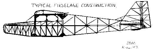
Determine the size of your fuselage. Cut the
bottoms out of two super market brown bags and cut
them at the vertical seam. On a big model tape two
bags together. Tape the paper print side down of
course and draw a center line across the middle of
the paper. That line will be your refernce line for
all other lines in your design. That line will be
used later for lining up the fuselage sides when
joined. Make this one line the darkest one in your
drawing.
Next determine the balsa stick size for the design
of the fuselage. To help you on this I'll give you a
guideline to follow based on what I used. Balsa stick
are all 36"long. On quarter scale you may want 48"
long balsa sheet stock to make the sticks out of.
Using the center line as the guide mark out the total length of the fuselage. Draw the outline of the model around the center line that runs from the center of the motor shaft at the nose, to the bottom of the horizontal stab/elevator at the rear.Use the concept drawing to get the outline as close as possible to it's shape. Using the guidelines above choose the size stick stock you will use. Draw that size stock on the center line using the center line as the top of the stick.
Draw the stick size on the out line all the way around except in the windshield and front hatch area. This section will be built into the fuselage during the build segment.
Draw your vertical sticks in place at the wing saddle area first.These sticks will be two pieces each due to the center line stick. This will be reinforced later.Draw in the wing saddle horizontal pieces next.
Here is another simple guide to follow on vertical stick spacing. Draw (4) evenly spaced vertical sticks between the wing saddle verticals. Draw in the vertical sticks aft of the wing saddle to the end of the tail at twice the spacing of the wing saddle vertical sticks. Draw the vertical sticks foreward of the wing saddle to the nose at half the spacing of the wing saddle verticals.
Draw angle braces between all the vertical stick using the same size sticks.
The area above the center line in the wing saddle area should be drawn in for the shape of the side windows if you plan to put in plastic ones.If they are made out of monokote trim over monokote the area can be built exactly like the area below the center line.
Draw in triangular gussets for wing dowel or just
for support at the front and rear corners of the
horizontal to vertical wing saddle sticks. If the
model has wing dowels make a note to make these
gussets out of 1/8 plywood. Draw in triangle shaped
gussets on both sides of the wing saddle verticals at
the bottom.
Draw in the front hatch and the windshield outline This assembly will be designed as it is built into the hatch and windshield opening later.
Draw the
nose
cowl balsa block to determine the thickness of the
block. This will be subassembled and drilled during
the build process and shaped on the fuselage.
VERTICAL STAB/RUDDER AND HORIZONTAL
STAB/ELEVATOR
=============================================
=============================================
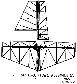
Using the concept drawing as the guide draw in the
vertical stab and rudder assembly using the same size
sticks as the fuselage. Double up the sticks on the
trailing vertical edge of the stab and on the leading
edge of the rudder to give depth for the hinge
inserts.Draw in (5) to (6) horizontal sticks closer
together at the bottom and spread out as they get to
the top. Do the same spacing on both the rudder and
the vertical stab.
In a separate area of the paper draw another rudder and stab with a mirror image attached and that would be the horizontal stab. Then add the elevator to that drawing.
Draw in a double stick at the trailing edge of the horizontal stab and the leading edge of the elevator for hinge mounting.
Add large gussets at the contol horn locations for the elevator and the rudder.
If your design calls for curved tailfeathers add sticks to accomodate the shape. Round tailfeathers do not fly any better!
Draw in
angular supports between the horizontal sticks on the
vertical stab and rudder and also on the horizontal
stab and elevator. These can be eliminated on smaller
airplanes 20 size and below.
WING DESIGN
=========================================
=========================================

=========================================
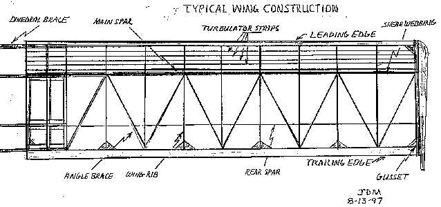
The wing saddle determines the size of the chord
of the wing on a constant chord wing. Draw in the
cross section of the wing rib with all the part that
can show from the side view. That would include the
leading edge, trailing edge, main spar, rear bottom
spar and the turbulator sticks. The length of the
wing is determined on what kind of wing loading you
want. Most electric planes fly better with light wing
loading so if you are building a 60 size plane and a
sample of a 60 size plane is at your field with a
tapered 62" wingspan a 62" constant chord wing would
be fine for the same length fuselage. You are better
off having a couple extra inches of wingspan then
not enough. Once you have determined the wingspan
length draw the main spar for half the wing at half
the length of course. Measure the wing chord allowing
room for the leading and trailing edge. I use (11)
ribs per wing half. (10) ribs evenly spaced and one
rib evenly spaced between the center rib and the next
rib out. This gives additional ribs to attach to for
reinforcement at the center. To determine the size of
the other parts needed for the wing use the matrix
below:
DESIGN MATRIX FOR STICK MODELS
Item----------- Small----Medium------Large
wingspan---------36-44-----46-54------56-72"
Gas engine-------049-09----15-40------45-60
Astro G motor----035-05----15-25------25-40
Fuselage sticks--1/8x1/8--3/16x3/16---1/4x1/4
Leading edge-----1/4x3/8--1/4x1/2-----1/4x3/4
Main spars-------1/4x1/4--1/4x3/8-----1/4x1/2
Rear spar--------1/8x1/8--1/4x1/4-----1/4x1/4
Trailing edge----1/4x1/4--1/4x3/8-----1/4x1/2
Wing rib thickness-1/16-----1/8----------1/8"
Turbulator stiks-1/16x1/16-1/8x1/8----1/8x1/8
Angle braces-----1/16x1/16-1/8x1/8----1/8x1/8
This same ratio will work well on any size air plane using the guide earlier on the size fuselage sticks to use on a particular size airplane. based on this, draw in all the remaining wing parts.
The ailerons extend in back of the wing saddle most of the time so they can be added last. The size of the ailerons is personal preference. I like big ones for good control and acrobatics.
Draw in the cross supports from the inside trailing edge to the opposite corner at the main spar.
Draw in 1/16 sheet stock as web shears with the grain running vertical from the rear of the top main spar to the rear of the bottom rear spar.You can thicken up the sheet stock to 1/8" on large airplanes.
Draw in (4) evenly space turbulator sticks between the top of the leading edge to the top main spar.
On the fuselage drawing add in all the side view parts of the wing including the rib, leading edge, main spar, rear spar bottom only. trailing edge and tubulator sticks on the top only.
==============================================
==============================================
On the wing draw in a 1/8 plywood dihedral brace at the following (4) locations: back of leading edge, back of main spar, front of rear spar and the front of the trailing edge. These run from the second rib out to the second rib on both sides.They will be covered further in the build section.
This
completes
the drawing enough to build the model. If you must
draw the top view of the fuselage refer to the build
section on determining width of the fuselage.
THIS IS THE END OF THE DESIGN SECTION

Click To The Next Section
Building Your Creation
Test Flying Your Own Design
Boomer's Electric Flight Home Page
Boomer's Links Page
Boomer's Pictures Page
Choosing A Project
