
WIRING
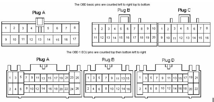
Whenever wiring is concerned the pins are counted left to right top to bottom while looking at the wire side of the female connector with the release for the connector at the top. Take a moment and picture that so you do it right as this is the way Honda does it and if everybody does it this way the world would be a better place! The only exceptions are noted on the diagrams that have the exceptions.
All connections that don’t need to come apart for any reason should be soldered and heat shrink to maintain stock reliability as many kinds of connectors come loose after vibrating and being exposed to the elements.
D16Z6 ECU wiring harness preparation:
Open up the cut up wiring harness’s loom from the donor car. All of the loom should be removed from the harness at this time so that you can easily access the wires.
Remove all wires that do not go to either the ECU connectors or the three main engine wiring harness connectors. You should just be able to pull them and they will slide out from the harness since they are not connected to anything. You shouldn’t have to cut anything at this point.
Make the #1 side A(male),15 pin connector as per the pin out below.
ECU connector (#1) Pin out side A (Male side)
These are the wires coming from the new ECU’s wiring harness that need to be spliced into existing wiring that is on the car already. Most of which are cut off of the stock ECU’s wiring harness.

4. Cut the wires off of C451 (Plug A), C452 (Plug B), and C453 (Plug C) connectors from stock ECU harness as you build the #1 side B(female),15 pin connector.
After you are sure that all the proper wires and connections have been made you can cut off the remaining wiring and pull out the stock ECU wiring harness. You will no longer need it after this point. Build the connector for this side B as per the pin out below.
Here is a picture of the three plugs that go to the ECU. The old plugs(OBD-0) are on top, and the new ones(OBD-1) on the bottom.
ECU connector (#1) Pin out side B (Female side) These are the wires that are cut off of the stock ECU wiring harness so that they can connect to the new ECU wiring harness
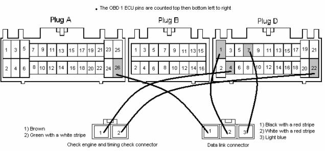
Also be sure to connect the ignition timing check and data check connectors at this point as you will not pass smog if you do not have them!!! They may be disconnected or partially disconnected due to cutting at this point. These are a two-pin connector and a three-pin connector near the ECU some of the wiring might not be connected anymore so you will have to splice it back in where it belongs on the ECU harness.
It’s not a big deal just follow the following wiring diagram here to verify that the connections are correctly made. The main thing to check is that pin 2 on the three pin connector has the wire running to a power source. I have chosen pin D1 as it is easy to access and in the same area saving you from running a wire somewhere to get 12Vs.
