Q-Vair Engine Mount
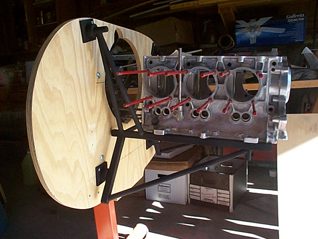
The firewall of the Q-2 is not very accommodating when it come to installing a traditional style engine mount. The Q's "factory" engine mount is basically 4 standoffs with rubber isolators. Since the location of these standoffs are very near the center of the firewall, the fact that the canard is up against the back side of the firewall does not come in to play. When trying to attach a standard type engine mount, it's best to try and make the lower attach points as low as possible on the firewall. But since the bottom 4" of the Q's firewall is not useable for this purpose (since this is where the canard's leading edge lives), the bottom attach points are very high. This is not a good thing. I considered that adding isolators to the underside of the engine would worsen the situation by lowering the top tube of the bed mount, making the bottom triangle very small. All I've read about engine mount design tells me that we need large equilateral triangles. The way I was headed, the best I could get for a triangle would be one with a short leg of about 4" with the other 2 legs being 18"-20". Not very equilateral. So I tested my theory and built a prototype. Below is the result. |
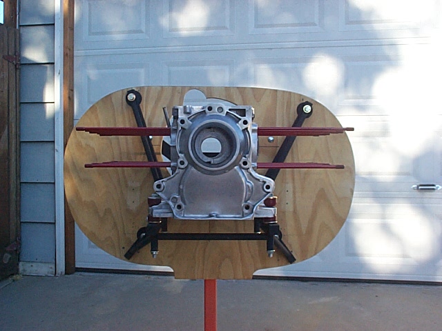
Notice that the engine is bolted directly to the bed mount. (Actually, the bolts are not in place but you should be able to see that the bottom of the case is resting directly on the bed). By standing the engine mount off the firewall, I opened myself to other issues. I made the bottom triangle as large as I could, by cantilevering it beyond it's firewall attach point. Although this made for a larger triangle, the attach point became a pivot point, and any downward force on the bed, caused the bed's top tube to pull away from the firewall. After building this prototype, I was able to visualize things much better, and determined that I did have room to mount isolators between the bottom of the case and the top of the bed mount. So I scrapped this one and started over with a more conventional design. |
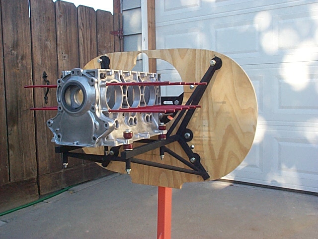
This second attempt still utilized extending the bottom triangle's base beyond the firewall attach point, but this time it's fulcrum action was minimized by the base of the triangle being bolted flat against the firewall. An additional attach point was added to arrest the bed's top tube from pulling away from the firewall as it did in the previous design. |
Another tube was added in this design. It's the one radiating from what should be the bottom firewall attach point, to the underside of the bed to case mounting point. This image also shows one of the characters of this engine. Notice that the rear cylinder position (defined by the stud bolts) on this side of the case is more aft than the cylinder on the other side of the case. This anomaly forced me to attach the tube coming from the upper firewall location to a location on the bed's top tube, considerably aft of where the case attaches to the bed. This is not good in my opinion, but it's the best I could do. |
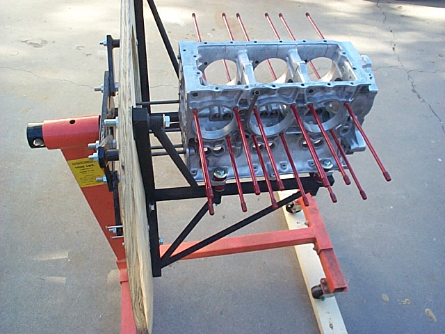
But notice that on this side of the case, I was able to attach that same tube to the bed's top rail, right where it should be attached. This is because the rear cylinder on this side of the engine is is further forward than the rear cylinder on the opposite side. |
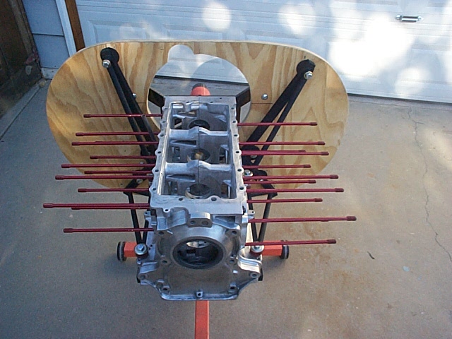
Another situation you might find odd is the lack of symmetry with the attachments to the firewall. |
Although the bottom attach points are symmetrical, the top
points are where they need to be to properly fit. First of all, they are
as high as I could get them. I figure it's naturally strong where the fuselage and
firewall meet, but it'll also be easy to reinforce this area. The second issue involved in locating these points is
interference with the accessories. The tubes run very close to the alternator (on
the right side as we look at this image) and the distributor (on the left side).
There's very little room to work. On the left side, the tube
|