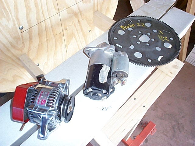
All 3 pieces: Starter and ring gear are from a Ford Probe 2.2L and
the alternator is from a Chevy Sprint |
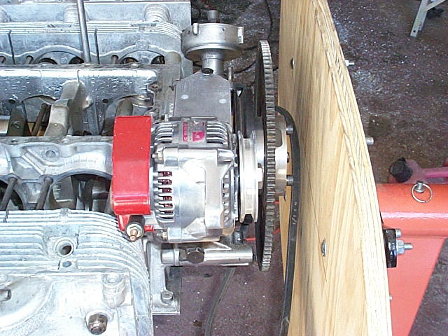
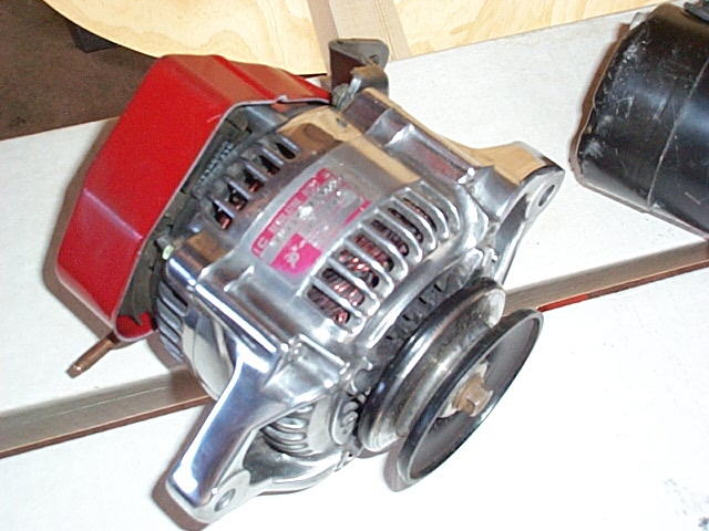 I polished the alternator,
and painted the regulator cover.
It's my understanding that this unit is good for 60 amps. |

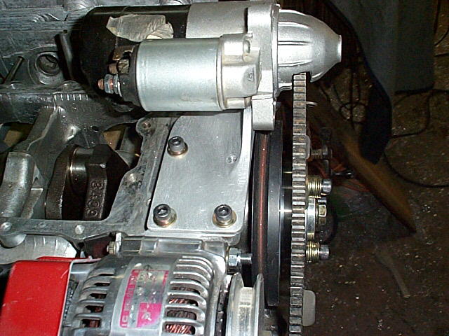
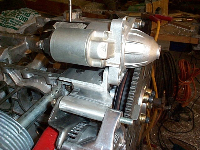
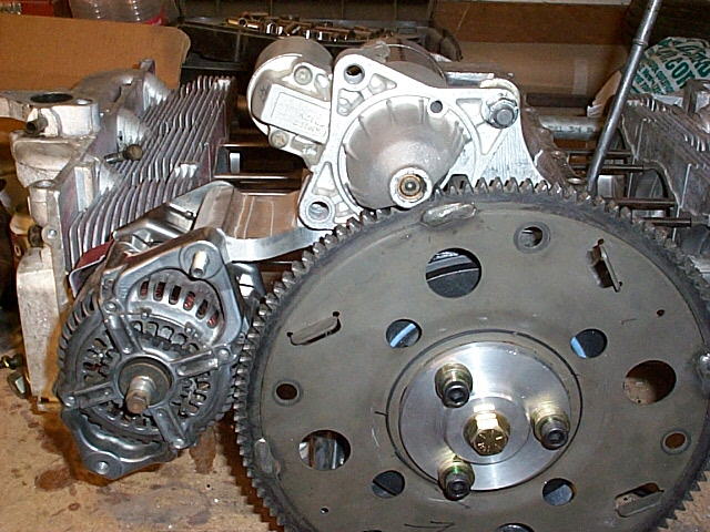
Very small starter. |
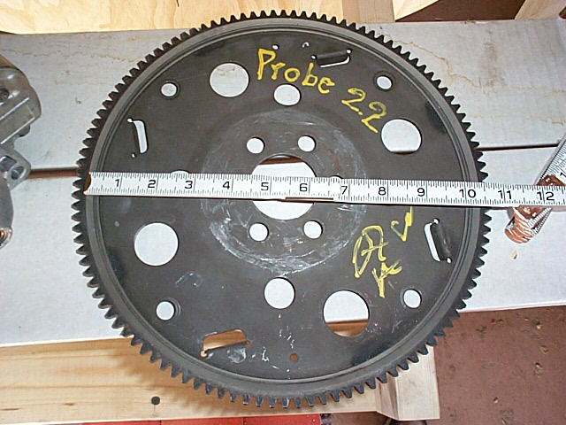
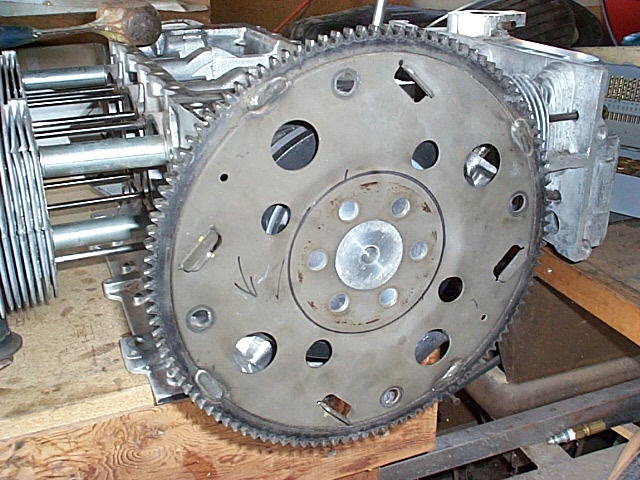
11" ring gear |
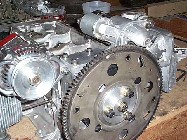
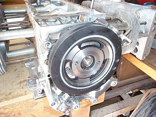
Facing the harmonic balancer. |
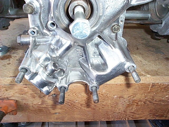
The studs holding the rear cover in place need to be removed or cut,
and the case cut back as well. I chose to remove my studs, but you can
see here how much of the case I had to remove. |
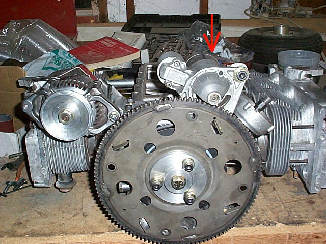
 Harmonic balancer in
place, studs removed. |
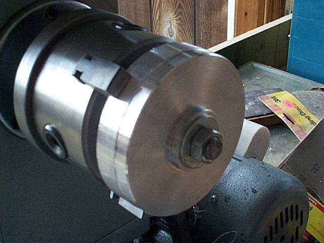
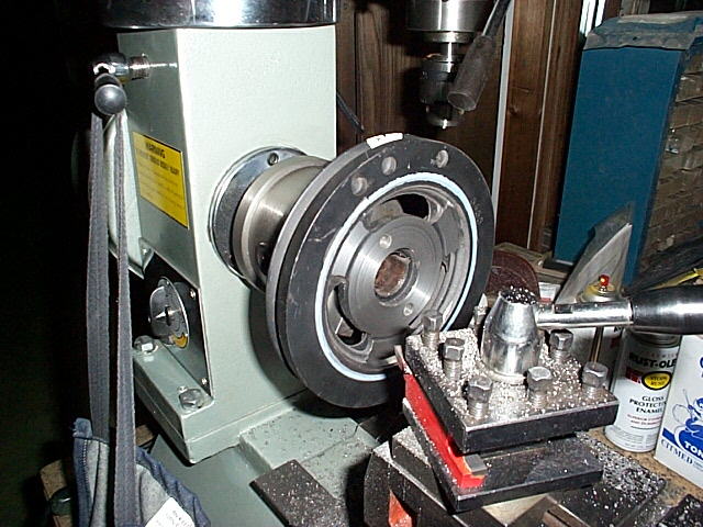
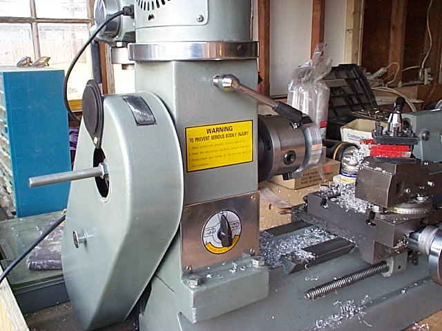
I found that if I ran a threaded rod through the lathe and nutted it at
both ends, I eliminated the chatter I was experiencing. This image shows the
threaded rod through the puck. |
...And this shot shows the other end of the rod and how it runs all the
way through the arbor. |
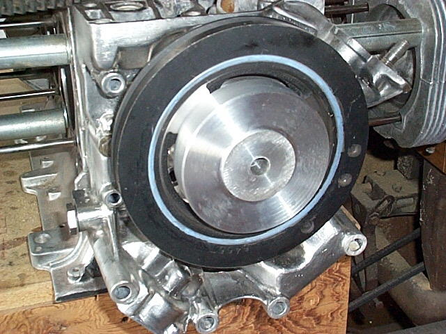
Here's the puck installed. It's a press fit into the harmonic
balancer.
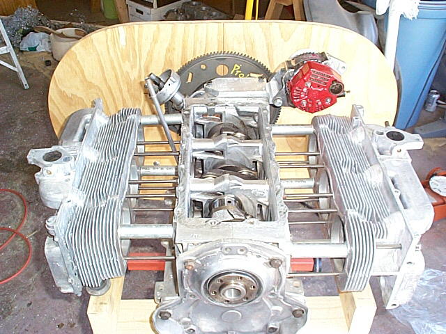
I'll be drilling holes through the squash plate, to align with 1/2 of the
holes in the ring gear, into new holes tapped in the spokes of the harmonic
balancer. |
The ring gear is pressed on to the boss turned into the puck
A combination squash plate / alternator pulley will be machined and through-bolted to the
harmonic balancer spokes.
|
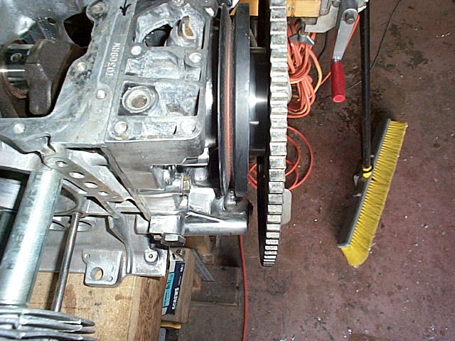
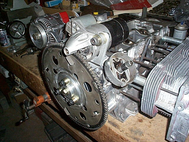
Here's the clearance between the back side of the teeth and the oil
pump. |
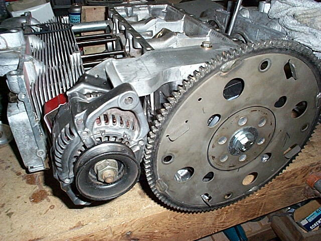
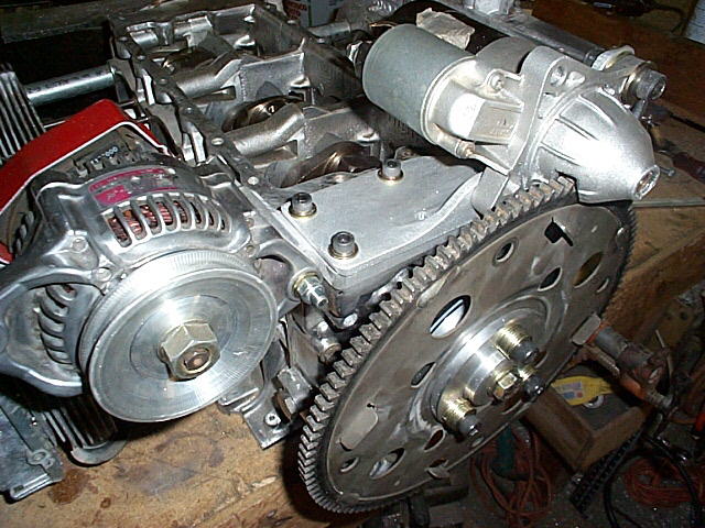
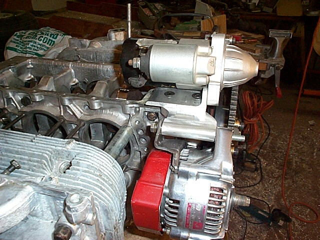
Here's the alternator mounted up. I needed it mounted to design
the pulley.
The bolt holding the ring gear in place is temporary. |
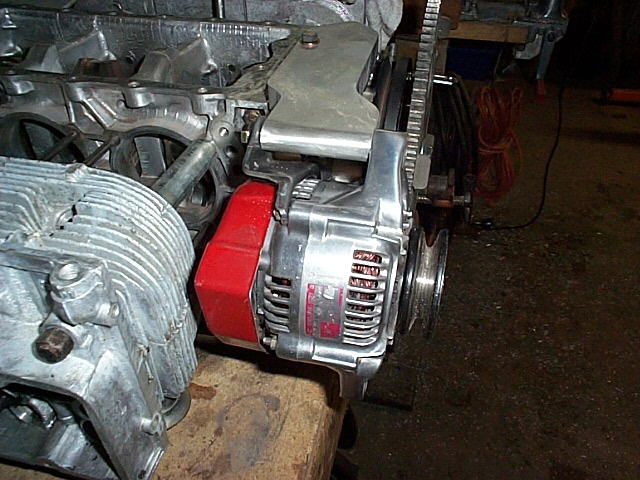
The bracket is temporarily mounted with 1 bolt. It'll become part
of the starter mount, probably the way Jon Crawford did his. It'll also be
relieved on the under side for the oil circuitry. |
| |
New
Stuff as of 4/30/00
The Starter is installed |
|

|
|
|